Difference between revisions of "PcDuino9"
(→I2C RTC) |
|||
| Line 1: | Line 1: | ||
| − | == | + | == Introduction == |
[[File:pcduino9 d.jpg|640px]] | [[File:pcduino9 d.jpg|640px]] | ||
| Line 7: | Line 7: | ||
[[File:pcduino9 c.jpg|640px]] | [[File:pcduino9 c.jpg|640px]] | ||
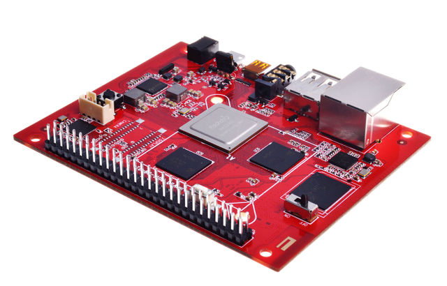
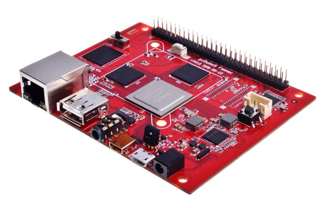
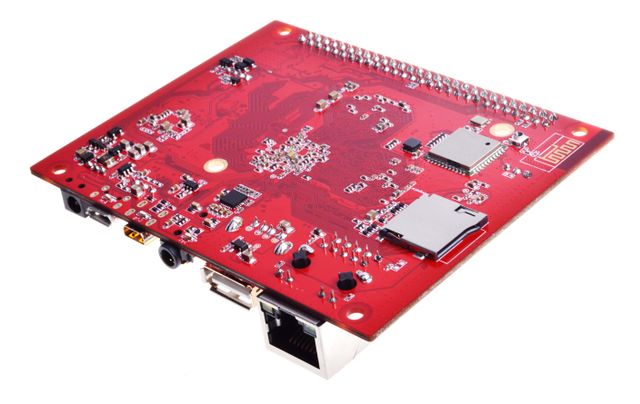
| − | + | PcDuino9 is a high-performance platform with powerful multi-threaded computing power, graphics processing and hardware decoding capabilities, and it supports Android and Ubuntu dual system, so it is also a powerful small computer, we hope that your creativity and inspiration will make it become more extraordinary. | |
| − | == | + | == Specifications == |
*CPU : Rockchip RK3288 ARM Corte-A17 Quad-Core up to 1.8GHz | *CPU : Rockchip RK3288 ARM Corte-A17 Quad-Core up to 1.8GHz | ||
| Line 35: | Line 35: | ||
*Board Size : 96 x 76 mm | *Board Size : 96 x 76 mm | ||
| − | == | + | == Hardware specifications == |
| − | *CPU: Rockchip RK3288 ARM Corte-A17 Quad-Core up to 1.8GHz | + | *CPU : Rockchip RK3288 ARM Corte-A17 Quad-Core up to 1.8GHz |
| − | *GPU: ARM Mali-T760 MP4 Support OpenGL ES 1.1/2.0 /3.0, OpenVG1.1, OpenCL1.1, Directx11 | + | *GPU : ARM Mali-T760 MP4 Support OpenGL ES 1.1/2.0 /3.0, OpenVG1.1, OpenCL1.1, Directx11 |
| − | * | + | *Memory : 1GB-4GB Dual-channel 32-bit LPDDR3 |
| − | * | + | *Storage : 8GB-16GB eMMC (Opt.), Micro SD slot support SDXC |
| − | * | + | *Ethernet : 10/100/1000Mbps Ethernet (RTL8211) |
| − | * | + | *USB : USB 2.0 Host x 2 (Opt.), USB OTG x 1 |
| − | * | + | *Video : HDMI2.0 support maximum 4K@60Hz display (Micro HDMI), LVDS/MIPI-DSI display interface |
| − | * | + | *Audio : 3.5mm audio In/Out |
| + | |||
| + | *Camera : MIPI-CSI camera interface | ||
| − | * | + | *WiFi/BT : AP6212 WiFi + BT module |
| − | == GPIOs | + | *IR: support infrared remote control function |
| + | |||
| + | *GPIO Extension : Raspberry Pi compatible GPIO, support UART, SPI, I2C BMC extension GPIO (Opt.), support ADC, PWM, UART, I2C | ||
| + | |||
| + | *Board Size : 96 x 76 mm | ||
| + | |||
| + | *Power supply: DC -5V / 2.5A | ||
| + | |||
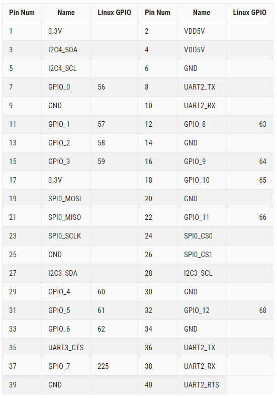
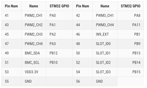
| + | == GPIOs mapping == | ||
[[File:pcduino 9 d.png|640px]] | [[File:pcduino 9 d.png|640px]] | ||
| Line 67: | Line 77: | ||
[[File:pcduino9 f.png|640px]] | [[File:pcduino9 f.png|640px]] | ||
| − | == | + | == Quick Start == |
| − | |||
| − | |||
| − | |||
| − | |||
| − | |||
| − | |||
| − | |||
| − | |||
| − | |||
| − | |||
| − | |||
| − | |||
| − | |||
| − | |||
| − | |||
| − | |||
| − | |||
| − | |||
| − | |||
| − | |||
| − | |||
| − | |||
| − | + | === 1.Write the system to eMMC by SD card === | |
| − | + | Download the image which named pcDuino9-SD-to-eMMC-xxx.img,use dd or Win32Disk,copy the image to SD card ,put the SD card on pcDuino9,and then pcDuino9 system on switch SD,that means switch the button “on” ,use ttl uart to watch system log,when kernel start,put the system on switch to “off”,then wait for all things done. | |
| + | System user name : linaro ,password:linaro | ||
| − | + | === 2.Write the system to eMMC on Linux === | |
| − | + | RK provides a command line tool of '''upgrade_tool''' under Linux, supporting for unified firmware '''update.img''' and partition image programming. | |
| − | + | There are two options for the open source tool: | |
| − | |||
| − | |||
| − | |||
| − | |||
| − | |||
| − | |||
| − | |||
| − | |||
| − | |||
| − | |||
| − | |||
| − | |||
| − | |||
| − | |||
| − | |||
| − | |||
| − | |||
| − | |||
| − | |||
| − | |||
| − | |||
| − | |||
| − | |||
| − | |||
| − | |||
| − | |||
| − | |||
| − | |||
| − | |||
| − | |||
| − | |||
| − | |||
| − | |||
| − | |||
| − | |||
| − | |||
*rkflashtool [https://github.com/Galland/rkflashtool_rk3066 https://github.com/Galland/rkflashtool_rk3066] | *rkflashtool [https://github.com/Galland/rkflashtool_rk3066 https://github.com/Galland/rkflashtool_rk3066] | ||
| Line 141: | Line 94: | ||
*rkflashkit [https://github.com/linuxerwang/rkflashkit https://github.com/linuxerwang/rkflashkit] | *rkflashkit [https://github.com/linuxerwang/rkflashkit https://github.com/linuxerwang/rkflashkit] | ||
| − | + | They only support the partition image programming, does not support a unified firmware. Rkflashtool is a command line tool, rkflashkit has a graphical interface and a command line support, which make it easier to use. The following only do an introduction of rkflashkit. There is no need to install the device driver for Linux, you can refer to the Windows chapter to connect the device. | |
'''upgrade_tool''' | '''upgrade_tool''' | ||
| − | + | Download Linux_Upgrade_Tool, and install to the system as the following method to be easy to call: | |
tar xf Linux_UpgradeTool_v1.2.tar.gz | tar xf Linux_UpgradeTool_v1.2.tar.gz | ||
| Line 152: | Line 105: | ||
sudo chown root:root /usr/local/bin/upgrade_tool | sudo chown root:root /usr/local/bin/upgrade_tool | ||
| − | + | Write unite firmware uxxxx.img: | |
sudo upgrade_tool uf update.img | sudo upgrade_tool uf update.img | ||
| − | + | Program partition image: | |
sudo upgrade_tool di -b /path/to/boot.img | sudo upgrade_tool di -b /path/to/boot.img | ||
| Line 164: | Line 117: | ||
sudo upgrade_tool di -m /path/to/misc.img | sudo upgrade_tool di -m /path/to/misc.img | ||
sudo upgrade_tool di resource /path/to/resource.img | sudo upgrade_tool di resource /path/to/resource.img | ||
| − | sudo upgrade_tool di -p paramater # | + | sudo upgrade_tool di -p paramater #Write parameter |
| − | sudo upgrade_tool ul bootloader.bin # | + | sudo upgrade_tool ul bootloader.bin #Write bootloader |
| + | |||
| − | + | If flash problems lead to an error during the upgrade, you can try low-level format or erase nand flash: | |
| − | sudo upgrade_tool lf # | + | sudo upgrade_tool lf # low-level format |
| − | sudo upgrade_tool ef # | + | sudo upgrade_tool ef # erase nand flash |
'''rkflashkit''' | '''rkflashkit''' | ||
| − | + | Installation: | |
sudo apt-get install build-essential fakeroot | sudo apt-get install build-essential fakeroot | ||
| Line 183: | Line 137: | ||
sudo dpkg -i rkflashkit_0.1.2_all.deb | sudo dpkg -i rkflashkit_0.1.2_all.deb | ||
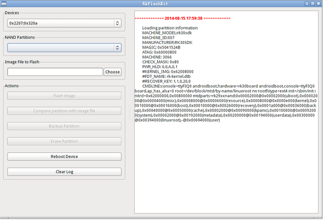
| − | + | Graphic interface: | |
sudo rkflashkit | sudo rkflashkit | ||
| Line 189: | Line 143: | ||
[[File:pcduino 9 l.png|640px]] | [[File:pcduino 9 l.png|640px]] | ||
| − | + | Command Line: | |
$ rkflashkit --help | $ rkflashkit --help | ||
| Line 202: | Line 156: | ||
sudo rkflashkit flash @boot boot.img @kernel.img kernel.img reboot | sudo rkflashkit flash @boot boot.img @kernel.img kernel.img reboot | ||
| − | === 3. | + | === 3.SD card boot system === |
| − | |||
| − | |||
| − | * | + | *Download the xxxx.img system image |
| − | * | + | *Prepare a memory card (C10 of more than 4GB) |
| − | * | + | *Use the dd command to copy the system to SD |
| − | + | *Insert the card into the pcDuino9, press the MASKROM button starting from the TF card to boot. | |
| − | + | === 4.pcDuino9 hardware operation === | |
| + | Hardware operation is based on '''NightWiring''', which is a hardware interface controlled by a cross-platform C ++ library, including UART, I2C, SPI and GPIO.Most of the code can be downloaded from wiringpi. GPIO is based on the function of the sysfs, it will be slightly slower, but very flexible. | ||
*git clone [https://github.com/nightseas/nightWiring.git https://github.com/nightseas/nightWiring.git] | *git clone [https://github.com/nightseas/nightWiring.git https://github.com/nightseas/nightWiring.git] | ||
| Line 223: | Line 176: | ||
sudo make install | sudo make install | ||
| − | ==== GPIO | + | ==== GPIO LED control ==== |
#include "nightWiring.h" | #include "nightWiring.h" | ||
| Line 265: | Line 218: | ||
} | } | ||
| − | ==== GPIO | + | ==== GPIO key input ==== |
#include "nightWiring.h" | #include "nightWiring.h" | ||
| Line 392: | Line 345: | ||
return 0; | return 0; | ||
} | } | ||
| − | |||
| − | |||
| − | |||
| − | |||
Revision as of 06:14, 19 January 2017
Introduction
PcDuino9 is a high-performance platform with powerful multi-threaded computing power, graphics processing and hardware decoding capabilities, and it supports Android and Ubuntu dual system, so it is also a powerful small computer, we hope that your creativity and inspiration will make it become more extraordinary.
Specifications
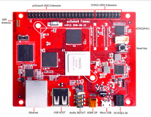
- CPU : Rockchip RK3288 ARM Corte-A17 Quad-Core up to 1.8GHz
- GPU : ARM Mali-T760 MP4 Support OpenGL ES 1.1/2.0 /3.0, OpenVG1.1, OpenCL1.1, Directx11
- Memory : 1GB-4GB Dual-channel 32-bit LPDDR3
- Storage : 8GB-16GB eMMC (Opt.), Micro SD slot support SDXC
- Ethernet : 10/100/1000Mbps Ethernet (RTL8211)
- USB : USB 2.0 Host x 2 (Opt.), USB OTG x 1
- Video : HDMI2.0 support maximum 4K@60Hz display (Micro HDMI), LVDS/MIPI-DSI display interface
- Audio : 3.5mm audio In/Out
- Camera : MIPI-CSI camera interface
- WiFi/BT : AP6212 WiFi + BT module
- GPIO Extension : Raspberry Pi compatible GPIO, support UART, SPI, I2C BMC extension GPIO (Opt.), support ADC, PWM, UART, I2C
- Board Size : 96 x 76 mm
Hardware specifications
- CPU : Rockchip RK3288 ARM Corte-A17 Quad-Core up to 1.8GHz
- GPU : ARM Mali-T760 MP4 Support OpenGL ES 1.1/2.0 /3.0, OpenVG1.1, OpenCL1.1, Directx11
- Memory : 1GB-4GB Dual-channel 32-bit LPDDR3
- Storage : 8GB-16GB eMMC (Opt.), Micro SD slot support SDXC
- Ethernet : 10/100/1000Mbps Ethernet (RTL8211)
- USB : USB 2.0 Host x 2 (Opt.), USB OTG x 1
- Video : HDMI2.0 support maximum 4K@60Hz display (Micro HDMI), LVDS/MIPI-DSI display interface
- Audio : 3.5mm audio In/Out
- Camera : MIPI-CSI camera interface
- WiFi/BT : AP6212 WiFi + BT module
- IR: support infrared remote control function
- GPIO Extension : Raspberry Pi compatible GPIO, support UART, SPI, I2C BMC extension GPIO (Opt.), support ADC, PWM, UART, I2C
- Board Size : 96 x 76 mm
- Power supply: DC -5V / 2.5A
GPIOs mapping
pcDuino9
BMC STM32F411
Quick Start
1.Write the system to eMMC by SD card
Download the image which named pcDuino9-SD-to-eMMC-xxx.img,use dd or Win32Disk,copy the image to SD card ,put the SD card on pcDuino9,and then pcDuino9 system on switch SD,that means switch the button “on” ,use ttl uart to watch system log,when kernel start,put the system on switch to “off”,then wait for all things done. System user name : linaro ,password:linaro
2.Write the system to eMMC on Linux
RK provides a command line tool of upgrade_tool under Linux, supporting for unified firmware update.img and partition image programming.
There are two options for the open source tool:
- rkflashtool https://github.com/Galland/rkflashtool_rk3066
- rkflashkit https://github.com/linuxerwang/rkflashkit
They only support the partition image programming, does not support a unified firmware. Rkflashtool is a command line tool, rkflashkit has a graphical interface and a command line support, which make it easier to use. The following only do an introduction of rkflashkit. There is no need to install the device driver for Linux, you can refer to the Windows chapter to connect the device.
upgrade_tool
Download Linux_Upgrade_Tool, and install to the system as the following method to be easy to call:
tar xf Linux_UpgradeTool_v1.2.tar.gz
cd Linux_UpgradeTool_v1.2
sudo mv upgrade_tool /usr/local/bin
sudo chown root:root /usr/local/bin/upgrade_tool
Write unite firmware uxxxx.img:
sudo upgrade_tool uf update.img
Program partition image:
sudo upgrade_tool di -b /path/to/boot.img
sudo upgrade_tool di -k /path/to/kernel.img
sudo upgrade_tool di -s /path/to/system.img
sudo upgrade_tool di -r /path/to/recovery.img
sudo upgrade_tool di -m /path/to/misc.img
sudo upgrade_tool di resource /path/to/resource.img
sudo upgrade_tool di -p paramater   #Write parameter
sudo upgrade_tool ul bootloader.bin #Write bootloader
If flash problems lead to an error during the upgrade, you can try low-level format or erase nand flash:
sudo upgrade_tool lf   # low-level format
sudo upgrade_tool ef   # erase nand flash
rkflashkit
Installation:
sudo apt-get install build-essential fakeroot
git clone https://github.com/linuxerwang/rkflashkit
cd rkflashkit
./waf debian
sudo apt-get install python-gtk2
sudo dpkg -i rkflashkit_0.1.2_all.deb
Graphic interface:
sudo rkflashkit
Command Line:
$ rkflashkit --help
Usage: <cmd> [args] [<cmd> [args]...]
part                              List partition
flash @<PARTITION> <IMAGE FILE>   Flash partition with image file
cmp @<PARTITION> <IMAGE FILE>     Compare partition with image file
backup @<PARTITION> <IMAGE FILE>  Backup partition to image file
erase  @<PARTITION>               Erase partition
reboot                            Reboot device
For example, flash device with boot.img and kernel.img, then reboot:
sudo rkflashkit flash @boot boot.img @kernel.img kernel.img reboot
3.SD card boot system
- Download the xxxx.img system image
- Prepare a memory card (C10 of more than 4GB)
- Use the dd command to copy the system to SD
- Insert the card into the pcDuino9, press the MASKROM button starting from the TF card to boot.
4.pcDuino9 hardware operation
Hardware operation is based on NightWiring, which is a hardware interface controlled by a cross-platform C ++ library, including UART, I2C, SPI and GPIO.Most of the code can be downloaded from wiringpi. GPIO is based on the function of the sysfs, it will be slightly slower, but very flexible.
cd nightWiring/
make -j4
sudo make install
GPIO LED control
#include "nightWiring.h"
#include "nightWiringGPIO.h"
#include "stdio.h"

static int fennecGpioMap[] = {

    /*  GPIO2_A0  */
            56,
    /*  GPIO2_A1,       GPIO2_A2,       GPIO2_A3,       GPIO2_A4    */
            57,             58,             59,             60,
    /*  GPIO2_A5,       GPIO2_A6,       GPIO7_B1,       GPIO2_A7    */
            61,             62,             225,            63,
    /*  GPIO2_B0,        GPIO2_B1,      GPIO2_B2,       GPIO2_B4    */
            64,             65,             66,             68,
    /*  GPIO2_B5,        GPIO7_B0,      GPIO7_A7,       GPIO7_B2    */
            69,             224,            223,            226
};

int ledMap[] = {2, 10, 3, 11};

int main(void)
{
    int i, j;
    nightWiringSetup();
    nightWiringGpioSetup(fennecGpioMap, 17);
    for(i=0; i<4; i++)
        pinMode(ledMap[i], OUTPUT);
    while(1)
    {
        for(i=0; i<4; i++)
        {
            for(j=0; j<4; j++)
                digitalWrite(ledMap[j], HIGH);
            digitalWrite(ledMap[i], LOW);
            delay(500);
        }
    }
    return 0;
}
GPIO key input
#include "nightWiring.h"
#include "nightWiringGPIO.h"
#include "stdio.h"

static int fennecGpioMap[] = {
    /*  GPIO2_A0  */
            56,
    /*  GPIO2_A1,       GPIO2_A2,       GPIO2_A3,       GPIO2_A4    */
            57,             58,             59,             60,
    /*  GPIO2_A5,       GPIO2_A6,       GPIO7_B1,       GPIO2_A7    */
            61,             62,             225,            63,
    /*  GPIO2_B0,        GPIO2_B1,      GPIO2_B2,       GPIO2_B4    */
            64,             65,             66,             68,
    /*  GPIO2_B5,        GPIO7_B0,      GPIO7_A7,       GPIO7_B2    */
            69,             224,            223,            226
};

int keyMap[] = {6, 13, 4, 12, 5};
char keyName[5][7] = {"UP\0", "CENTER\0", "DOWN\0", "LEFT\0", "RIGHT\0"};

int readKey(int num)
{
    int key = digitalRead(keyMap[num]);
    if(key == LOW)
    {
        // Delay for a while and re-detect the key status
        // Filtering glitches on the signal
        delay(10);
        if(key == LOW)
            return 1;
    }

    return 0;
}

int main(void)
{
    int i;
    nightWiringSetup();
    nightWiringGpioSetup(fennecGpioMap, 17);
    for(i=0; i<5; i++)
        pinMode(keyMap[i], INPUT);
    while(1)
    {
        for(i=0; i<5; i++)
        {
            if(readKey(i))
            {
                printf("Key %s is pressed!\n", keyName[i]);
                delay(500);
            }
        }
    }
    return 0;
}
I2C RTC
#include "nightWiring.h"

#include "nightWiringI2C.h"

#include "stdio.h"

#define DS1307_ADDR 0x68

int i2cFd;
int quitFlag = 0;

unsigned char DEC2BCD(unsigned char val)
{
  return ( (val/10*16) + (val%10) );

}

unsigned char BCD2DEC(unsigned char val)
{
   return ( (val/16*10) + (val%16) );
}


void rtcSetTime(unsigned char year, unsigned char month, unsigned char date, unsigned char dayofWeek, unsigned char hour, unsigned char min ,unsigned   char sec)
{
  unsigned char reg = 0x00;
  i2cWriteReg8(i2cFd, 0x00, DEC2BCD(sec));
  i2cWriteReg8(i2cFd, 0x01, DEC2BCD(min));
  i2cWriteReg8(i2cFd, 0x02, DEC2BCD(hour));
  i2cWriteReg8(i2cFd, 0x03, DEC2BCD(dayofWeek));
  i2cWriteReg8(i2cFd, 0x04, DEC2BCD(date));
  i2cWriteReg8(i2cFd, 0x05, DEC2BCD(month));
  i2cWriteReg8(i2cFd, 0x06, DEC2BCD(year));
}

void rtcGetTime()
{
  unsigned char year, month, date, dayofWeek, hour, min ,sec;
  unsigned char reg = 0x00;
  sec       = BCD2DEC(i2cReadReg8(i2cFd, 0x00) & 0x7f);
  min       = BCD2DEC(i2cReadReg8(i2cFd, 0x01));
  hour      = BCD2DEC(i2cReadReg8(i2cFd, 0x02) & 0x3f);
  dayofWeek = BCD2DEC(i2cReadReg8(i2cFd, 0x03));
  date      = BCD2DEC(i2cReadReg8(i2cFd, 0x04));
  month     = BCD2DEC(i2cReadReg8(i2cFd, 0x05));
  year      = BCD2DEC(i2cReadReg8(i2cFd, 0x06));
  printf("Time: %02d-%02d-%02d  %02d:%02d:%02d.\n", year, month, date, hour, min ,sec);
}

int main(void)
{
    int i;
    if((i2cFd=i2cSetup("/dev/i2c-4", DS1307_ADDR)) < 0)
    {
        printf("Error: I2C acess failed! i2cSetup() return %d\n",i2cFd);
        return 0;
    }
    printf("I2C interface init complete.\n");
    printf("Writing time 2016-10-01 Sat 21:10:00 to RTC...\n");
    rtcSetTime(16,10,1,6,21,10,0);
    while(1)
    {
        rtcGetTime();
        delay(1000);
    }
    return 0;
}
