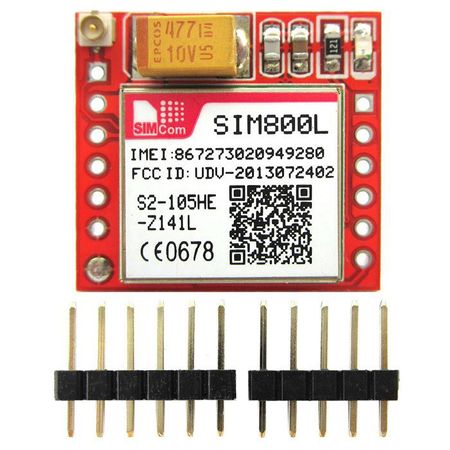
SIM800L Quad-band Network Mini GPRS GSM Breakout Module
Contents
Introductiom
Mini GSM / GPRS breakout board is based on SIM800L module, supports quad-band GSM/GPRS network, available for GPRS and SMS message data remote transmission.The board features compact size and low current consumption. With power saving technique, the current consumption is as low as 1mA in sleep mode.It communicates with microcontroller via UART port, supports command including 3GPP TS 27.007, 27.005 and SIMCOM enhanced AT Commands. It's operating voltage: 3.7 ~ 4.2V , peak current: 1A .
Features
- Quad-band 850/900/1800/1900MHz
- Connect onto any global GSM network with any 2G SIM (in the USA, T- Mobile is suggested).
- Make and receive voice calls using a headset or an external 8 speaker and electret microphone.
- Send and receive SMS messages.
- Send and receive GPRS data (TCP/IP, HTTP, etc.) .
- Scan and receive FM radio broadcasts.
- Lead out buzzer and vibrational motor control port.
- AT command interface with "auto baud" detection.
QUICKSTART SIM800L WITH ARDUINO
SIM800 is one of the most commonly used GSM module among hobbyists and Arduino community. Even though AT command reference is available with a quick Google search, it is not very easy for a beginner to properly understand and use Arduino with SIM800. Therefore, this post summarizes how a beginner could interact with SIM800 using Arduino and in few future posts we’ll be going ahead with several other real life use cases discussing how SIM800 can be used with Arduino effectively.
Wiring
Caution! :SIM800 module itself uses input voltage of 3.7V – 4.2V. Therefore, if you directly connect the Vcc pin to Arduino 5V pin, it might damage the module as well. I tried 3.3V Arduino pin with no luck. Therefore if you have the SIM800 module itself, you will have to get the input voltage in range, maybe with a LM317 (and few calculations with a LM317 calculator).
Fortunately I am using below module with voltage regulators built in :
For above module Arduino to SIM800 connectivity was pretty straight forward .
- SIM800 5v/4v ↔ Arduino 5v
- SIM800 GND (either one) ↔ Arduino GND
- SIM800 SIM_TXD ↔ Arduino D8 (read through for the reason)
- SIM800 SIM_RXD ↔ Arduino D7 (read through for the reason)
Connect module with Arduino as mentioned above or with any changes depending on the module being used. Insert a valid SIM card and connect the Arduino with Arduino IDE.
Simple Serial Communication
Below is the simplest program usable to interact with SIM800 :
#include <SoftwareSerial.h>

//SIM800 TX is connected to Arduino D8
#define SIM800_TX_PIN 8

//SIM800 RX is connected to Arduino D7
#define SIM800_RX_PIN 7

//Create software serial object to communicate with SIM800
SoftwareSerial serialSIM800(SIM800_TX_PIN,SIM800_RX_PIN);

void setup() {
  //Begin serial comunication with Arduino and Arduino IDE (Serial Monitor)
  Serial.begin(9600);
  while(!Serial);

  //Being serial communication witj Arduino and SIM800
  serialSIM800.begin(9600);
  delay(1000);

  Serial.println("Setup Complete!");
}

void loop() {
  //Read SIM800 output (if available) and print it in Arduino IDE Serial Monitor
  if(serialSIM800.available()){
    Serial.write(serialSIM800.read());
  }
  //Read Arduino IDE Serial Monitor inputs (if available) and send them to SIM800
  if(Serial.available()){
    serialSIM800.write(Serial.read());
  }
}
Download
How to buy
Here to buy Mini GPRS GSM Breakout Module on store
