|
|
| (9 intermediate revisions by the same user not shown) |
| Line 27: |
Line 27: |
| | | | |
| | == HardWare set up == | | == HardWare set up == |
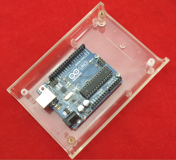
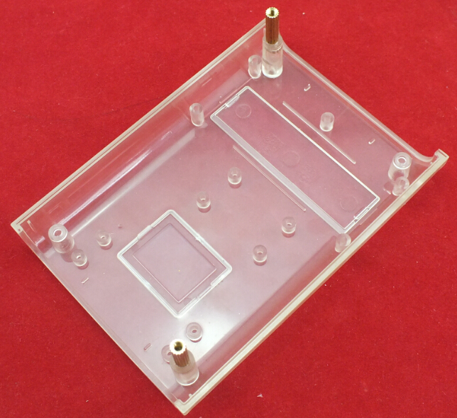
| − | 1. Fixing the Arduino UNO in the clear box by screws. | + | 1. Fixing the Arduino UNO in the LinkSprite Clear Enclosure by screws. |
| | | | |
| − | [[File:Hardware set up1.jpg]] | + | [[File:Hardware set up1.JPG]] |
| | | | |
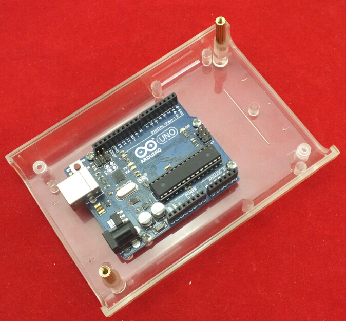
| − | 2. | + | 2. Fixing 2 pcs Copper Pillar in the Clear Enclosure |
| | | | |
| − | == Specifications ==
| + | [[File:Hardware set up2.JPG]] |
| | | | |
| − | <table border="1" cellspacing="0" width="80%">
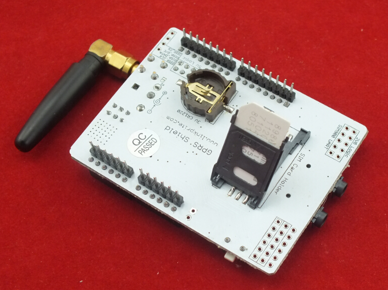
| + | 3. Insert a SIM card in SIM GSM/GPRS Shield |
| | | | |
| − | <tr>
| + | [[File:Hardware set up3.JPG]] |
| − | <th scope="col" style="width: 40%" align="center"> Item
| |
| − | </th><th scope="col" align="center"> Min
| |
| − | </th><th scope="col" align="center"> Typical
| |
| − | </th><th scope="col" align="center"> Max
| |
| − | </th><th scope="col" align="center"> Unit
| |
| − | </th></tr>
| |
| − | <tr>
| |
| − | <th scope="row"> Voltage
| |
| − | </th><td align="center">4.8
| |
| − | </td><td align="center">5.0
| |
| − | </td><td align="center">5.2
| |
| − | </td><td align="center">VDC
| |
| − | </td></tr>
| |
| − | <tr>
| |
| − | <th scope="row"> Current
| |
| − | </th><td align="center">/
| |
| − | </td><td align="center">50
| |
| − | </td><td align="center">450
| |
| − | </td><td align="center">mA
| |
| − | </td></tr>
| |
| − | <tr>
| |
| − | <th scope="row"> Dimension(with antenna)
| |
| − | </th><td align="center" colspan="3"> 110x58x19
| |
| − | </td><td align="center">mm
| |
| − | </td></tr>
| |
| − | <tr>
| |
| − | <th scope="row"> Net Weight
| |
| − | </th><td align="center" colspan="3"> 76±2
| |
| − | </td><td align="center">g
| |
| − | </td></tr></table>
| |
| | | | |
| − | == Interface Function ==
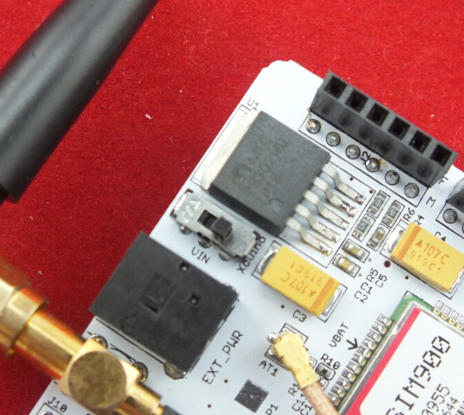
| + | 4. Push the power supply to Xduino |
| | | | |
| − | '''Power select''' - select the power supply for GPRS shield(external power or 5v of arduino)<br>
| + | [[File:Hardware set up4.JPG]] |
| − | '''Power jack''' - connected to external 4.8~5VDC power supply<br>
| |
| − | '''Antenna interface''' - connected to external antenna<br>
| |
| − | '''Serial port select''' - select either software serial port or hareware serial port to be connected to GPRS Shield<br>
| |
| − | '''Hardware Serial''' - D0/D1 of Arduino/Seeeduino<br>
| |
| − | '''Software serial''' - D7/D8 of Arduino/Seeeduino only<br>
| |
| − | '''Status LED''' - tell whether the power of SIM900 is on<br>
| |
| − | '''Net light''' - tell the status about SIM900 linking to the net<br>
| |
| − | '''UART of SIM900''' - UART pins breakout of SIM900<br>
| |
| − | '''Microphone''' - to answer the phone call<br>
| |
| − | '''Speaker''' - to answer the phone call<br>
| |
| − | '''GPIO,PWM and ADC of SIM900''' - GPIO,PWM and ADC pins breakout of SIM900<br>
| |
| − | '''Power key''' - power up and down for SIM900
| |
| | | | |
| − | === Pins usage on Arduino ===
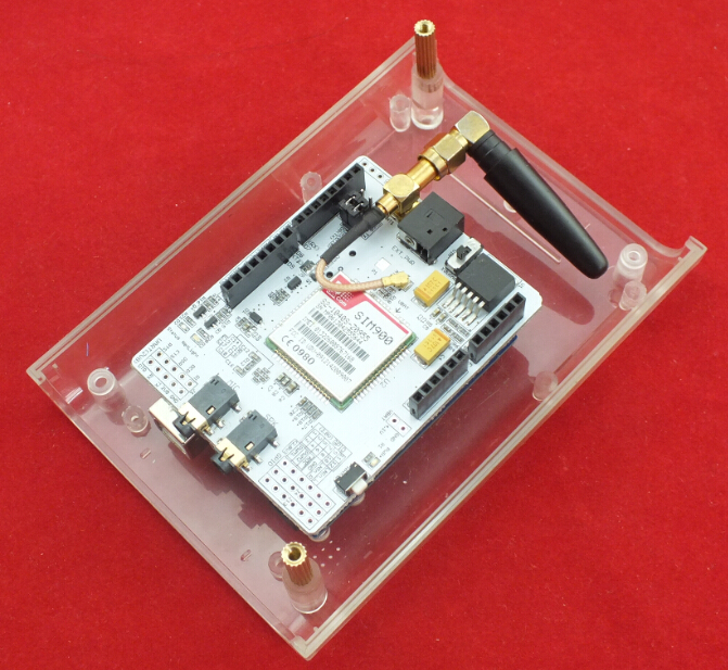
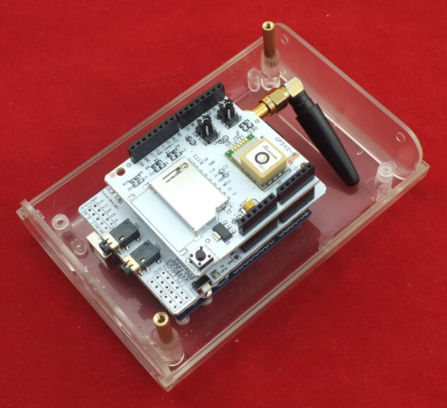
| + | 5. Plug SIM GSM/GPRS Shield into Arduino UNO |
| | | | |
| − | '''D0''' - Unused if you select software serial port to communicate with GPRS Shield<br>
| + | [[File:Hardware set up5.JPG]] |
| − | '''D1''' - Unused if you select software serial port to communicate with GPRS Shield<br>
| |
| − | '''D2''' - Unused<br>
| |
| − | '''D3''' - Unused<br>
| |
| − | '''D4''' - Unused<br> '''D5''' - Unused<br> '''D6''' - Unused<br>
| |
| − | '''D7''' - Used if you select software serial port to communicate with GPRS Shield<br>
| |
| − | '''D8''' - Used if you select software serial port to communicate with GPRS Shield<br>
| |
| − | '''D9''' - Used for software control the power up or down of the SIM900<br>
| |
| − | '''D10''' - Unused<br>
| |
| − | '''D11''' - Unused<br>
| |
| − | '''D12''' - Unused<br>
| |
| − | '''D13''' - Unused<br>
| |
| − | '''D14(A0)''' - Unused<br> '''D15(A1)''' - Unused<br> '''D16(A2)''' - Unused<br> '''D17(A3)''' - Unused<br> '''D18(A4)''' - Unused<br> '''D19(A5)''' - Unused<br>
| |
| − | '''Note:''' A4 and A5 are connected to the I2C pins on the SIM900. The SIM900 however cannot be accessed via the I2C .
| |
| | | | |
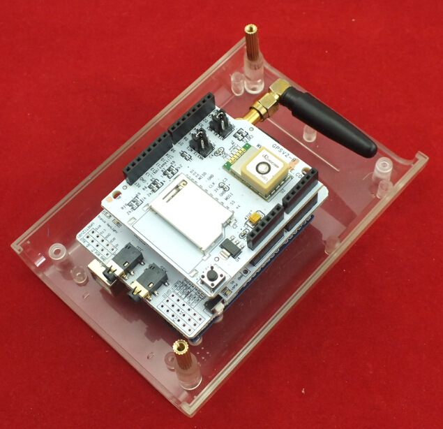
| | + | 6. Plug GPS Shield into SIM GSM/GPRS Shield |
| | | | |
| − | == A Simple Source Code Example ==
| + | [[File:Hardware set up6.JPG]] |
| | | | |
| − | The demo code below is for the Arduino to send SMS message/dial a voice call/submit a http request to a website and upload datas to the pachube. It has been tested on Arduino Duemilanove but will work on any compatible variant, plesse note that this sketch uses the sorfware UART of ATmega328P. please follow the following steps for running this sketch.
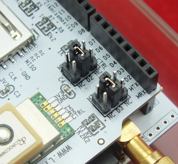
| + | 7. Choose the D2 and D3 of GPS Shield as the picture showen |
| − | *With the GPRS Shield removed, download this sketch into your Arduino.
| |
| − | *Disconnect the Xduino from USB port to remove power source.
| |
| − | *Set the Serial Port jumpers on the GPRS Shield in SWserial position, to use the Soft Serial port of Arduino.
| |
| − | *Connect the antenna to the GPRS Shield and insert the SIM Card.
| |
| − | *Mount the GPRS Shield on Arduino.
| |
| − | *Connect the Arduino to the computer by USB, and fire up your favorite serial terminal software on computer, choose the COM port for Arduino, set it to operate at 19200 8-N-1.
| |
| − | *Type command in the terminal to execute different function, threr are 4 functions in the demo:
| |
| − | **If you input 't', the demo will send a SMS message to another cellphone which you set(you need set the number in the code);
| |
| − | **If you input 'd', the program will dial a call to the other cellphone that you set(it is also need you set in the code );
| |
| − | **If you input 'h', it will submit a http request to a web that you want to access(it need you set the web adress in the code), it will return a string from the website if it goes correctly;
| |
| − | **If you input 's', it will upload the datas to the pachube(for detail you can refer to the explanation in the code). I strongly recommend you input 'h' before input 's', because uploading data to the pachube need do some setting, after execute the function of submit a http request, the setting will be set.
| |
| − | *If the program returns error in the terminal after you typed the command, don't worry, just try input the command again.
| |
| | | | |
| − | Note:
| + | [[File:Hardware set up7.JPG]] |
| | | | |
| − | (1) The GPRS/GSM shield need external power supply to guarantee reliable operations.
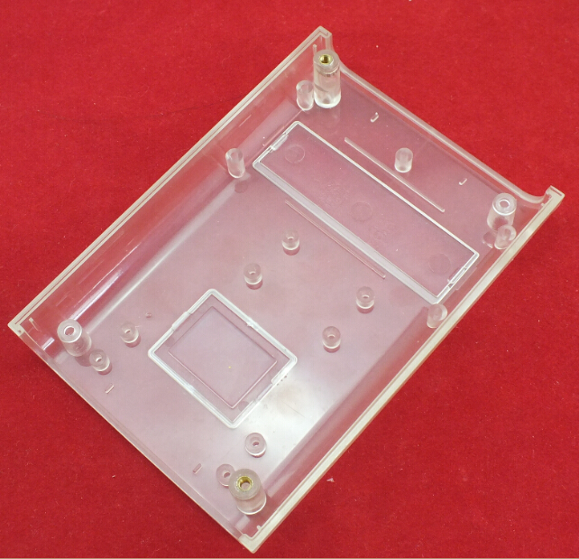
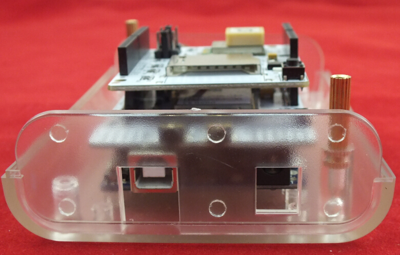
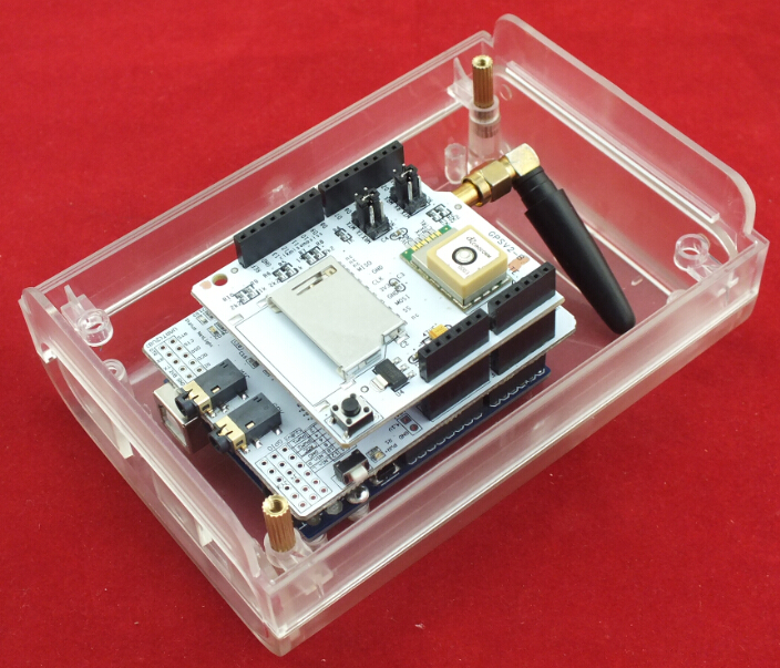
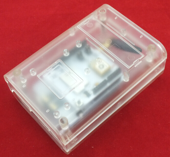
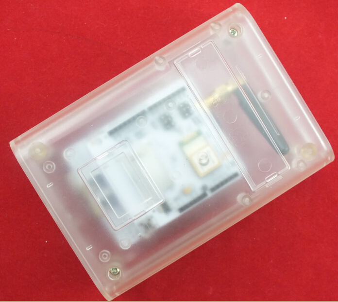
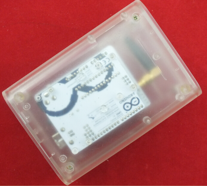
| + | 8. Assembled the Clear Enclosure |
| | | | |
| − | (2) After attaching the shield to Arduino board and adding power supply, you need press the power button on the shield for about 2 seconds to turn on the shield.
| + | [[File:Hardware set up8.JPG]] |
| | | | |
| | + | [[File:Hardware set up9.JPG]] |
| | | | |
| − | <syntaxhighlight lang="c">
| + | [[File:Hardware set up10.JPG]] |
| | | | |
| − | /*Note: this code is a demo for how to using gprs shield to send sms message, dial a voice call and
| + | [[File:Hardware set up11.JPG]] |
| − | send a http request to the website, upload data to pachube.com by TCP connection,
| |
| − |
| |
| − | The microcontrollers Digital Pin 7 and hence allow unhindered
| |
| − | communication with GPRS Shield using SoftSerial Library.
| |
| − | IDE: Arduino 1.0 or later
| |
| − | Replace the following items in the code:
| |
| − | 1.Phone number, don't forget add the country code
| |
| − | 2.Replace the Access Point Name
| |
| − | 3. Replace the Pachube API Key with your personal ones assigned
| |
| − | to your account at cosm.com
| |
| − | */
| |
| − |
| |
| − |
| |
| − | #include <SoftwareSerial.h>
| |
| − | #include <String.h>
| |
| − |
| |
| − | SoftwareSerial mySerial(7, 8);
| |
| − |
| |
| − | void setup()
| |
| − | {
| |
| − | mySerial.begin(19200); // the GPRS baud rate
| |
| − | Serial.begin(19200); // the GPRS baud rate
| |
| − | delay(500);
| |
| − | }
| |
| − |
| |
| − | void loop()
| |
| − | {
| |
| − | //after start up the program, you can using terminal to connect the serial of gprs shield,
| |
| − | //if you input 't' in the terminal, the program will execute SendTextMessage(), it will show how to send a sms message,
| |
| − | //if input 'd' in the terminal, it will execute DialVoiceCall(), etc.
| |
| − |
| |
| − | if (Serial.available())
| |
| − | switch(Serial.read())
| |
| − | {
| |
| − | case 't':
| |
| − | SendTextMessage();
| |
| − | break;
| |
| − | case 'd':
| |
| − | DialVoiceCall();
| |
| − | break;
| |
| − | case 'h':
| |
| − | SubmitHttpRequest();
| |
| − | break;
| |
| − | case 's':
| |
| − | Send2Pachube();
| |
| − | break;
| |
| − | }
| |
| − | if (mySerial.available())
| |
| − | Serial.write(mySerial.read());
| |
| − | }
| |
| − |
| |
| − | ///SendTextMessage()
| |
| − | ///this function is to send a sms message
| |
| − | void SendTextMessage()
| |
| − | {
| |
| − | mySerial.print("AT+CMGF=1\r"); //Because we want to send the SMS in text mode
| |
| − | delay(100);
| |
| − | mySerial.println("AT + CMGS = \"+86138xxxxx615\"");//send sms message, be careful need to add a country code before the cellphone number
| |
| − | delay(100);
| |
| − | mySerial.println("A test message!");//the content of the message
| |
| − | delay(100);
| |
| − | mySerial.println((char)26);//the ASCII code of the ctrl+z is 26
| |
| − | delay(100);
| |
| − | mySerial.println();
| |
| − | }
| |
| − |
| |
| − | ///DialVoiceCall
| |
| − | ///this function is to dial a voice call
| |
| − | void DialVoiceCall()
| |
| − | {
| |
| − | mySerial.println("ATD + +86138xxxxx615;");//dial the number
| |
| − | delay(100);
| |
| − | mySerial.println();
| |
| − | }
| |
| − |
| |
| − | ///SubmitHttpRequest()
| |
| − | ///this function is submit a http request
| |
| − | ///attention:the time of delay is very important, it must be set enough
| |
| − | void SubmitHttpRequest()
| |
| − | {
| |
| − | mySerial.println("AT+CSQ");
| |
| − | delay(100);
| |
| − |
| |
| − | ShowSerialData();// this code is to show the data from gprs shield, in order to easily see the process of how the gprs shield submit a http request, and the following is for this purpose too.
| |
| − |
| |
| − | mySerial.println("AT+CGATT?");
| |
| − | delay(100);
| |
| − |
| |
| − | ShowSerialData();
| |
| − |
| |
| − | mySerial.println("AT+SAPBR=3,1,\"CONTYPE\",\"GPRS\"");//setting the SAPBR, the connection type is using gprs
| |
| − | delay(1000);
| |
| − |
| |
| − | ShowSerialData();
| |
| − |
| |
| − | mySerial.println("AT+SAPBR=3,1,\"APN\",\"CMNET\"");//setting the APN, the second need you fill in your local apn server
| |
| − | delay(4000);
| |
| − |
| |
| − | ShowSerialData();
| |
| − |
| |
| − | mySerial.println("AT+SAPBR=1,1");//setting the SAPBR, for detail you can refer to the AT command mamual
| |
| − | delay(2000);
| |
| − |
| |
| − | ShowSerialData();
| |
| − |
| |
| − | mySerial.println("AT+HTTPINIT"); //init the HTTP request
| |
| − |
| |
| − | delay(2000);
| |
| − | ShowSerialData();
| |
| − |
| |
| − | mySerial.println("AT+HTTPPARA=\"URL\",\"www.google.com.hk\"");// setting the httppara, the second parameter is the website you want to access
| |
| − | delay(1000);
| |
| − |
| |
| − | ShowSerialData();
| |
| − |
| |
| − | mySerial.println("AT+HTTPACTION=0");//submit the request
| |
| − | delay(10000);//the delay is very important, the delay time is base on the return from the website, if the return datas are very large, the time required longer.
| |
| − | //while(!mySerial.available());
| |
| − |
| |
| − | ShowSerialData();
| |
| − |
| |
| − | mySerial.println("AT+HTTPREAD");// read the data from the website you access
| |
| − | delay(300);
| |
| − |
| |
| − | ShowSerialData();
| |
| − |
| |
| − | mySerial.println("");
| |
| − | delay(100);
| |
| − | }
| |
| − |
| |
| − | ///send2Pachube()///
| |
| − | ///this function is to send the sensor data to the pachube, you can see the new value in the pachube after execute this function///
| |
| − | void Send2Pachube()
| |
| − | {
| |
| − | mySerial.println("AT+CGATT?");
| |
| − | delay(1000);
| |
| − |
| |
| − | ShowSerialData();
| |
| − |
| |
| − | mySerial.println("AT+CSTT=\"CMNET\"");//start task and setting the APN,
| |
| − | delay(1000);
| |
| − |
| |
| − | ShowSerialData();
| |
| − |
| |
| − | mySerial.println("AT+CIICR");//bring up wireless connection
| |
| − | delay(3000);
| |
| − |
| |
| − | ShowSerialData();
| |
| − |
| |
| − | mySerial.println("AT+CIFSR");//get local IP adress
| |
| − | delay(2000);
| |
| − |
| |
| − | ShowSerialData();
| |
| − |
| |
| − | mySerial.println("AT+CIPSPRT=0");
| |
| − | delay(3000);
| |
| − |
| |
| − | ShowSerialData();
| |
| − |
| |
| − | mySerial.println("AT+CIPSTART=\"tcp\",\"api.cosm.com\",\"8081\"");//start up the connection
| |
| − | delay(2000);
| |
| − |
| |
| − | ShowSerialData();
| |
| − |
| |
| − | mySerial.println("AT+CIPSEND");//begin send data to remote server
| |
| − | delay(4000);
| |
| − | ShowSerialData();
| |
| − | String humidity = "1031";//these 4 line code are imitate the real sensor data, because the demo did't add other sensor, so using 4 string variable to replace.
| |
| − | String moisture = "1242";//you can replace these four variable to the real sensor data in your project
| |
| − | String temperature = "30";//
| |
| − | String barometer = "60.56";//
| |
| − | mySerial.print("{\"method\": \"put\",\"resource\": \"/feeds/42742/\",\"params\"");//here is the feed you apply from pachube
| |
| − | delay(500);
| |
| − | ShowSerialData();
| |
| − | mySerial.print(": {},\"headers\": {\"X-PachubeApiKey\":");//in here, you should replace your pachubeapikey
| |
| − | delay(500);
| |
| − | ShowSerialData();
| |
| − | mySerial.print(" \"_cXwr5LE8qW4a296O-cDwOUvfddFer5pGmaRigPsiO0");//pachubeapikey
| |
| − | delay(500);
| |
| − | ShowSerialData();
| |
| − | mySerial.print("jEB9OjK-W6vej56j9ItaSlIac-hgbQjxExuveD95yc8BttXc");//pachubeapikey
| |
| − | delay(500);
| |
| − | ShowSerialData();
| |
| − | mySerial.print("Z7_seZqLVjeCOmNbEXUva45t6FL8AxOcuNSsQS\"},\"body\":");
| |
| − | delay(500);
| |
| − | ShowSerialData();
| |
| − | mySerial.print(" {\"version\": \"1.0.0\",\"datastreams\": ");
| |
| − | delay(500);
| |
| − | ShowSerialData();
| |
| − | mySerial.println("[{\"id\": \"01\",\"current_value\": \"" + barometer + "\"},");
| |
| − | delay(500);
| |
| − | ShowSerialData();
| |
| − | mySerial.println("{\"id\": \"02\",\"current_value\": \"" + humidity + "\"},");
| |
| − | delay(500);
| |
| − | ShowSerialData();
| |
| − | mySerial.println("{\"id\": \"03\",\"current_value\": \"" + moisture + "\"},");
| |
| − | delay(500);
| |
| − | ShowSerialData();
| |
| − | mySerial.println("{\"id\": \"04\",\"current_value\": \"" + temperature + "\"}]},\"token\": \"lee\"}");
| |
| − |
| |
| − |
| |
| − | delay(500);
| |
| − | ShowSerialData();
| |
| − |
| |
| − | mySerial.println((char)26);//sending
| |
| − | delay(5000);//waitting for reply, important! the time is base on the condition of internet
| |
| − | mySerial.println();
| |
| − |
| |
| − | ShowSerialData();
| |
| − |
| |
| − | mySerial.println("AT+CIPCLOSE");//close the connection
| |
| − | delay(100);
| |
| − | ShowSerialData();
| |
| − | }
| |
| − |
| |
| − | void ShowSerialData()
| |
| − | {
| |
| − | while(mySerial.available()!=0)
| |
| − | Serial.write(mySerial.read());
| |
| − | }
| |
| − | </syntaxhighlight>
| |
| | | | |
| − | '''AT Command Tester Application'''
| + | [[File:Hardware set up12.JPG]] |
| | | | |
| − | [http://m2msupport.net/m2msupport/module-tester/ AT Command Tester] is a free online tool test [http://m2msupport.net/m2msupport/software-and-at-commands-for-m2m-modules/ AT Commands] and other modem functionalities of [http://m2msupport.net/m2msupport/category/devices/gprs-modem/ 2G modules] (GPRS/EDGE) , [http://m2msupport.net/m2msupport/category/devices/gprs-modem/ 3G Modules] (HSDPA/EVDO) and [http://m2msupport.net/m2msupport/search-page/?Max!Download!Speed=100%20Mbps 4G Modules] (LTE).AT Command Tester tool connects to the modem port of the device and can test various modem functions such as getting [http://m2msupport.net/m2msupport/at-commands-to-get-device-information/ device information], [http://m2msupport.net/m2msupport/data-call-at-commands-to-set-up-gprsedgeumtslte-data-call/ gprs data call], [http://m2msupport.net/m2msupport/voice-call-at-commands-to-set-up-voice-call/ voice call],[http://m2msupport.net/m2msupport/at-command-for-http-functions-for-remote-server-data-access/ http access], [http://m2msupport.net/m2msupport/signal-quality/ checking signal condition], [http://m2msupport.net/m2msupport/network-registration/ network registration], [http://m2msupport.net/m2msupport/sms-at-commands/ SMS functions], [http://m2msupport.net/m2msupport/sim-at-commands-for-sim-presense-and-status/ SIM access], [http://m2msupport.net/m2msupport/sim-phonebook-at-commands/ phonebook functions] etc. | + | [[File:Hardware set up13.JPG]] |
| | | | |
| − | In the 'Port Configuration' section of the tool, users can search for available ports using the 'Find Ports' button. Then using the 'Connect' button, users can connect to the modem port of the device.
| + | [[File:Hardware set up14.JPG]] |
| | | | |
| − | In the 'Command Mode' tab of AT Command Tester, single AT commands can be sent. The drop down list provides AT command description and examples. Users can modify the default command settings.
| + | [[File:Hardware set up15.JPG]] |
| | | | |
| − | [[File:M2m img1.PNG]]
| + | == Programming the Arduino == |
| | + | Before you can program the Arduino Uno, you must first install the Tiny GPS library for the GPS Shield. |
| | + | These are the steps to install the library: |
| | | | |
| | + | 1. Download the [https://github.com/mikalhart/TinyGPS/releases/tag/v13 Tiny GPS library] for the Arduino. |
| | | | |
| − | Under the 'Script Mode' tab, multiple AT commands can be sent at a time. Users can add descriptive comments and save the script on their local machine.
| + | 2. Extract the zip file to the folder: " Arduinobraries " |
| | | | |
| − | [[File:Script mode.PNG]]
| + | 3. Now you would see the library under " Sketch --> Import Library " in the Arduino IDE. |
| | | | |
| − | Data Call
| + | 4. You can proceed with the Arduino Uno programming. |
| | | | |
| − | To make a data call with the modem, you need to connect to the APN of the carrier network. The carrier APN and other required information are stored in the SIM card and are referred as PDP contexts. Typically multiple PDP contexts are stored in the SIM for different call types. With the AT Command Tester you can edit/add/delete PDP contexts in a easy to use user interface.
| |
| | | | |
| − | [[Image:Datacall.PNG]] | + | Download the [https://github.com/linksprite/gctk/blob/master/gctk.ino code] and load it on the Arduino |
| | | | |
| | + | == Testing == |
| | | | |
| − | <br>Typical call setup sequence,
| + | Now that you have built the system, it is time to install it in your vehicle. The device can be installed anywhere in the car: the hood, cabin or trunk. Remember that the device must be hidden from view and difficult to locate by a car thief. The device must directly be connected to the 12v Car battery as it must run even when the car is switched off. |
| | | | |
| − | [http://m2msupport.net/m2msupport/atcgdcont-define-pdp-context/ AT+CGDCONT?]
| + | Steps to track down your vehicle using the system: |
| | | | |
| − | +CGDCONT: 1,"IP","epc.tmobile.com","0.0.0.0",0,0<br>+CGDCONT: 2,"IP","test5","0.0.0.0",0,0<br>+CGDCONT: 3,"IP","","0.0.0.0",0,0
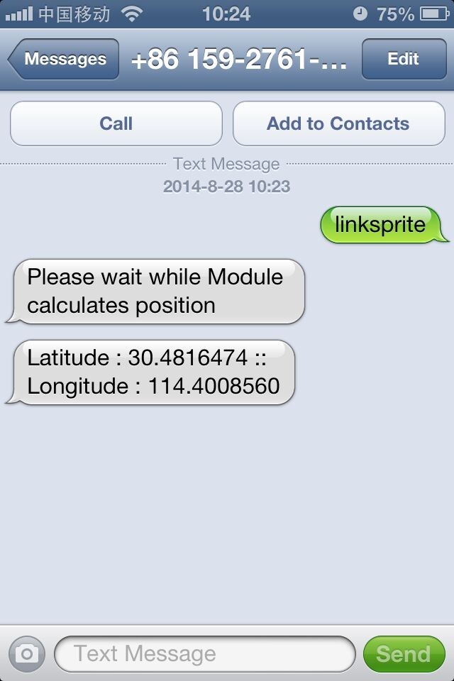
| + | 1. When your car is stolen and you wish to track your car, simply send a text message containing the password to your car. |
| | | | |
| − | OK<br>Checking registration status...
| + | 2. It then verifies the password you entered with the password stored in its program. If the password matches, then system sends an acknowledgment SMS to the predefined phone/cell number stored in it. |
| | | | |
| − | [http://m2msupport.net/m2msupport/atcreg-network-registration/ AT+CREG?]
| + | 3. GPS then begins to calculate its GPS position and once a GPS lock is acheived, it sends the coordinates of its location to the number stored in its program. |
| | | | |
| − | +CREG: 0,1
| + | [[File:Txt.jpg]] |
| | | | |
| − | OK<br>The device is registered in home network.
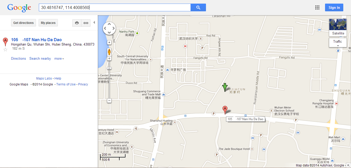
| + | 4. After you receive the Coordinates in your message, copy them to the search bar in google maps to reveal the position of your stolen car. |
| | | | |
| − | Checking if device is already connected...
| + | [[File:Map.png]] |
| | + | |
| | | | |
| − | [http://m2msupport.net/m2msupport/atcgact-pdp-context-activate-or-deactivate/ AT+CGACT?]
| |
| | | | |
| − | +CGACT: 1,0<br>+CGACT: 2,0<br>+CGACT: 3,0
| + | And there you go...congratulations!!! You have built your very own Global Car Tracking System. |
| − | | |
| − | OK<br>[http://m2msupport.net/m2msupport/atcmee-report-mobile-termination-error/ AT+CMEE=1]
| |
| − | | |
| − | OK<br>Attaching to network...<br>AT+CGATT=1
| |
| − | | |
| − | OK
| |
| − | | |
| − | Connecting...
| |
| − | | |
| − | [http://m2msupport.net/m2msupport/atcgact-pdp-context-activate-or-deactivate/ AT+CGACT=1, 1]
| |
| − | | |
| − | OK<br>Connect Sucessful
| |
| − | | |
| − | <br> '''SMS'''
| |
| − | | |
| − | The SMS tab of the 'AT Command Tester' tool provides the interfaces to send SMS messages. You can also list/view/delete SMS messages stored on the SIM.
| |
| − | | |
| − | [[Image:Sms.PNG]] <br> General sequence for sending SMS message,
| |
| − | | |
| − | Checking registration status...
| |
| − | | |
| − | [http://m2msupport.net/m2msupport/atcreg-network-registration/ AT+CREG?]
| |
| − | | |
| − | +CREG: 0,1
| |
| − | | |
| − | OK<br>The device is registered in home network.
| |
| − | | |
| − | AT+CMGS="858XXXXXXX"
| |
| − | | |
| − | > Test Message with AT Command Tester�
| |
| − | | |
| − | +CMGS: 19
| |
| − | | |
| − | OK<br>SMS Send successful
| |
| − | | |
| − | '''Network Selection''' - This tab allows the user to manually select available networks. Modems are typically set for automatic network selection. 'Find Networks' button will command the modem to scan for available networks.
| |
| − | | |
| − | [[Image:Network selection.PNG]]
| |
| − | | |
| − | <br>
| |
| − | | |
| − | AT+COPS command will initiate network scan in the modem,
| |
| − | | |
| − | Finding Networks. Please wait..
| |
| − | | |
| − | [http://m2msupport.net/m2msupport/atcops-plmn-selection/ AT+COPS=?]
| |
| − | | |
| − | +COPS: (2,"T-Mobile","T-Mobile","310260"),(1,"AT&T","AT&T","310410"),,(0,1,4),(0,1,2)
| |
| − | | |
| − | OK<br>Networks found
| |
| − | | |
| − | <br>
| |
| − | | |
| − | '''Phonebook'''<br>
| |
| − | | |
| − | With the 'Phone Book' tab, you can add/delete/read phone book entries stored on the SIM,
| |
| − | | |
| − | [[Image:Phone book.PNG]]
| |
| − | | |
| − | Getting phonebook entries..
| |
| − | | |
| − | [http://m2msupport.net/m2msupport/atcpbr-read-phonebook-entries/ AT+CPBR=1,99]
| |
| − | | |
| − | +CPBR: 1,"*233",129,"Refill Now"
| |
| − | | |
| − | +CPBR: 2,"#999#",255,"Check Balance"
| |
| − | | |
| − | +CPBR: 3,"8878878878",129,"Test"
| |
| − | | |
| − | OK<br>
| |
| − | | |
| − | '''SIM900 HTTP'''
| |
| − | | |
| − | With the 'HTTP' tab, you can read the bearer profiles and test HTTP GET and HTTP POST,
| |
| − | | |
| − | [[Image:Http.PNG]]
| |
| − | | |
| − | Getting Bearer profiles..
| |
| − | | |
| − | AT+SAPBR=4,1
| |
| − | | |
| − | +SAPBR: <br>CONTYPE: GPRS<br>APN: <br>PHONENUM: <br>USER: <br>PWD: <br>RATE: 2
| |
| − | | |
| − | OK<br>AT+SAPBR=4,2
| |
| − | | |
| − | +SAPBR: <br>CONTYPE: GPRS<br>APN: <br>PHONENUM: <br>USER: <br>PWD: <br>RATE: 2
| |
| − | | |
| − | OK<br>AT+SAPBR=4,3
| |
| − | | |
| − | +SAPBR: <br>CONTYPE: GPRS<br>APN: <br>PHONENUM: <br>USER: <br>PWD: <br>RATE: 2
| |
| − | | |
| − | OK
| |
| − | | |
| − | <br>Checking registration status...
| |
| − | | |
| − | [http://m2msupport.net/m2msupport/atcreg-network-registration/ AT+CREG?]
| |
| − | | |
| − | +CREG: 0,1
| |
| − | | |
| − | OK<br>The device is registered in home network.
| |
| − | | |
| − | Querying bearer 1 .
| |
| − | | |
| − | AT+SAPBR=2,1
| |
| − | | |
| − | +SAPBR: 1,1,"162.184.222.162"
| |
| − | | |
| − | OK<br>Bearer 1 is Connected.IP address is "162.184.222.162"
| |
| − | | |
| − | Bearer 1 is Connected.
| |
| − | | |
| − | Initializing HTTP service...
| |
| − | | |
| − | [http://m2msupport.net/m2msupport/athttpinit-initialize-http-service/ AT+HTTPINIT]
| |
| − | | |
| − | OK<br>Error initializing HTTP service.
| |
| − | | |
| − | Setting up HTTP parameters..
| |
| − | | |
| − | [http://m2msupport.net/m2msupport/athttppara-set-paramaters-for-http-connection/ AT+HTTPPARA]="URL","http://www.m2msupport.net/m2msupport/http_get_test.php"
| |
| − | | |
| − | OK<br>[http://m2msupport.net/m2msupport/athttppara-set-paramaters-for-http-connection/ AT+HTTPPARA]="CID",1[[|]]
| |
| − | | |
| − | OK<br>[http://m2msupport.net/m2msupport/athttpaction-perform-getposthead-http-action/ AT+HTTPACTION]=0
| |
| − | | |
| − | OK
| |
| − | | |
| − | HTTP GET is sucessful
| |
| − | | |
| − | [http://m2msupport.net/m2msupport/athttpread-get-response-from-http-server/ AT+HTTPREAD]
| |
| − | | |
| − | +HTTPREAD:58<br>Sucessful HTTP GET test. Data received from m2msupport.net<br>OK<br>Terminating HTTP session..
| |
| − | | |
| − | [http://m2msupport.net/m2msupport/athttpterm-terminate-the-http-session/ AT+HTTPTERM]
| |
| − | | |
| − | OK
| |
| − | | |
| − | <br>
| |
| − | | |
| − | '''SIM900 FTP'''<br>
| |
| − | | |
| − | FTP Get and Put with SIM900 module can be tested as shown below,
| |
| − | | |
| − | [[Image:Ftp.PNG]]
| |
| − | | |
| − | <br>
| |
| − | | |
| − | Checking registration status...
| |
| − | | |
| − | AT+CREG?
| |
| − | | |
| − | +CREG: 0,1
| |
| − | | |
| − | OK<br>The device is registered in home network.
| |
| − | | |
| − | Querying bearer 1 .
| |
| − | | |
| − | AT+SAPBR=2,1
| |
| − | | |
| − | +SAPBR: 1,1,"162.184.222.162"
| |
| − | | |
| − | OK<br>Bearer 1 is Connected.IP address is "162.184.222.162"
| |
| − | | |
| − | Bearer 1 is Connected.
| |
| − | | |
| − | Setting up FTP parameters..
| |
| − | | |
| − | [http://m2msupport.net/m2msupport/atftpcid-set-ftp-bearer-profile-identifier/ AT+FTPCID]=1
| |
| − | | |
| − | OK
| |
| − | | |
| − | <br>[http://m2msupport.net/m2msupport/atftpserv-set-up-ftp-server-address/ AT+FTPSERV]="ftp.m2msupport.net"
| |
| − | | |
| − | OK<br>[http://m2msupport.net/m2msupport/atftpun-set-up-ftp-user-name/ AT+FTPUN]="xxxxxx"
| |
| − | | |
| − | OK<br>[http://m2msupport.net/m2msupport/atftppw-sets-up-ftp-password/ AT+FTPPW]="xxxxxxx"
| |
| − | | |
| − | OK<br>[http://m2msupport.net/m2msupport/atftpgetname-set-download-file-name/ AT+FTPGETNAME]="ftptest.txt"
| |
| − | | |
| − | OK<br>[http://m2msupport.net/m2msupport/atftpgetpath-set-the-ftp-download-file-path/ AT+FTPGETPATH]="/www/m2msupport/"
| |
| − | | |
| − | OK<br>[http://m2msupport.net/m2msupport/atftpget-set-download-file/ AT+FTPGET]=1
| |
| − | | |
| − | OK
| |
| − | | |
| − | <br>+FTPGET:1,1<br>FTP session sucessfully started
| |
| − | | |
| − | [http://m2msupport.net/m2msupport/atftpget-set-download-file/ AT+FTPGET]=2,1024
| |
| − | | |
| − | +FTPGET:2,784<br>2-11-16 10:53:34.769 -----------------------------------------------<br>eclipse.buildId=M20120914-1800<br>java.version=1.6.0_16<br>java.vendor=Sun Microsystems Inc.<br>BootLoader constants: OS=win32, ARCH=x86, WS=win32, NL=en_US<br>Framework arguments: -product org.eclipse.epp.package.java.product<br>Command-line arguments: -os win32 -ws win32 -arch x86 -product org.eclipse.epp.package.java.product
| |
| − | | |
| − | !ENTRY org.eclipse.m2e.logback.appender 4 0 2012-11-16 12:11:54.493<br>!MESSAGE Unable to update index for central|http://repo.maven.apache.org/maven2: C:\Users\sgobi\.m2\repository\.cache\m2e\1.2.0\26522e0d83a422eed93329ece7565cfc\nexus-maven-repository-index.zip (The system cannot find the file specified) | |
| − | | |
| − | !ENTRY org.eclipse.jdt.ui 4 10001 2012-11-16 13:21:21.138<br>!MESSAGE Internal Error<br>!STACK 1<br>OK<br>[http://m2msupport.net/m2msupport/atftpget-set-download-file/ AT+FTPGET]=2,1024 | |
| − | | |
| − | +FTPGET:2,0
| |
| − | | |
| − | OK<br>FTP data transfer is complete
| |
| − | | |
| − | <br>+FTPGET:1,0<br>FTP session end<br>
| |
| | | | |
| | == How to buy == | | == How to buy == |
| − | Here to buy SIM900 GPRS/GSM Shield on [http://store.linksprite.com/sim900-gprs-gms-shield/ store]
| |
| − |
| |
| − | == FAQ ==
| |
| − |
| |
| − | == Resources ==
| |
| − | *[https://s3.amazonaws.com/linksprite/Shields/SIM900_GPRS/GPRSshield_Schematic.pdf GPRS Shield v1.4 Schematic]
| |
| − | *[https://s3.amazonaws.com/linksprite/Shields/SIM900_GPRS/SIM900_ATC_V1_00.pdf AT Commands v1.00] & [https://s3.amazonaws.com/linksprite/Shields/SIM900_GPRS/SIM900_AT_Command_Manual_V1.03.pdf AT Commands v1.03] & [https://s3.amazonaws.com/linksprite/Shields/SIM900_GPRS/SIM900_HD_V1.05.pdf Hardware Design] - SIM900 Documentation
| |
| − | *[https://s3.amazonaws.com/linksprite/Shields/SIM900_GPRS/si5902bd.pdf Si5902BDC] - Dual N-Channel 30 V (D-S) MOSFETs (used for 2.8V <> 5.0V translation for Serial Interface)
| |
| − | *[https://s3.amazonaws.com/linksprite/Shields/SIM900_GPRS/SIM900_firmware_and_tool.zip SIM900 firmware and tool](firmware:1137B08SIM900M64_ST) for firmware upgrade
| |
| − | *[https://s3.amazonaws.com/linksprite/Shields/SIM900_GPRS/1137B09SIM900M64_ST.zip firmware:1137B09SIM900M64_ST]
| |
| − | *[https://s3.amazonaws.com/linksprite/Shields/SIM900_GPRS/SIM900datasheeet.zip SIM900datasheeet]
| |
| − | *[http://learn.linksprite.com/?p=1992 Tutorial – Arduino and SIM900 GSM Modules]
| |
| − |
| |
| − | == Introduction ==
| |
| − |
| |
| − |
| |
| − | == Part List ==
| |
| − |
| |
| − |
| |
| − | == Tools ==
| |
