Difference between revisions of "WRTnode"
| Line 1: | Line 1: | ||
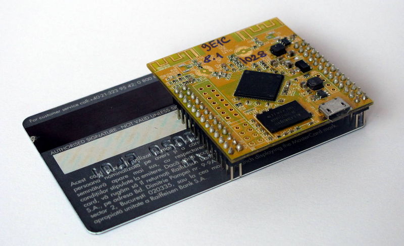
== Introduction == | == Introduction == | ||
| + | |||
| + | [[File:1.jpg]] | ||
WRTnode, which is based on Wi-Fi AP-Soc, is an open source development board hardware. There is a [http://www.mediatek.com/] MT7620n chip in it. | WRTnode, which is based on Wi-Fi AP-Soc, is an open source development board hardware. There is a [http://www.mediatek.com/] MT7620n chip in it. | ||
| Line 24: | Line 26: | ||
== Specifications == | == Specifications == | ||
Hardware parameters | Hardware parameters | ||
| + | |||
[[File:2.jpg]] | [[File:2.jpg]] | ||
| + | |||
*45mm*50mm | *45mm*50mm | ||
*MTK MT7620N 580MHz MIPS CPU (MIPS24KEc) | *MTK MT7620N 580MHz MIPS CPU (MIPS24KEc) | ||
| Line 56: | Line 60: | ||
Click the pic to see full resolution version. | Click the pic to see full resolution version. | ||
Perspective A pin map | Perspective A pin map | ||
| + | |||
[[File:3.jpg]] | [[File:3.jpg]] | ||
| + | |||
[[File:4.jpg]] | [[File:4.jpg]] | ||
== Starting guide == | == Starting guide == | ||
What you will get? | What you will get? | ||
| + | |||
[[File:5.jpg]] | [[File:5.jpg]] | ||
| + | |||
You get the WRTnode in a very nice transparent plastic box, inside the box you get WRTnode stickers too. The box is useful to store various small items useful for WRTnode (USB memory stick, I2C port expander module, jumpers and so on). | You get the WRTnode in a very nice transparent plastic box, inside the box you get WRTnode stickers too. The box is useful to store various small items useful for WRTnode (USB memory stick, I2C port expander module, jumpers and so on). | ||
| + | |||
[[File:6.jpg]] [[File:7.jpg]] | [[File:6.jpg]] [[File:7.jpg]] | ||
| + | |||
[[File:8.jpg]] | [[File:8.jpg]] | ||
Besides these, you get: | Besides these, you get: | ||
The 'special' USB cable customized for WRTnode | The 'special' USB cable customized for WRTnode | ||
| + | |||
[[File:9.jpg]] | [[File:9.jpg]] | ||
| + | |||
[[File:10.jpg]] | [[File:10.jpg]] | ||
| + | |||
The micro USB standard plug will be connected to the WRTnode board and to power the board itself. | The micro USB standard plug will be connected to the WRTnode board and to power the board itself. | ||
The USB standard type A plug will be connected to any USB wall adapter, any PC USB port, any USB 5Vdc power supply (at least 500mA (0,5A) current). | The USB standard type A plug will be connected to any USB wall adapter, any PC USB port, any USB 5Vdc power supply (at least 500mA (0,5A) current). | ||
The USB standard type A receptacle can connect any USB device to the WRTnode board, for example can connect a USB memory stick: | The USB standard type A receptacle can connect any USB device to the WRTnode board, for example can connect a USB memory stick: | ||
| + | |||
[[File:11.jpg]] | [[File:11.jpg]] | ||
| + | |||
Or a USB webcam like this: | Or a USB webcam like this: | ||
| + | |||
[[File:12.jpg]] | [[File:12.jpg]] | ||
| + | |||
Or you can connect many more USB devices at once through a USB hub like this: | Or you can connect many more USB devices at once through a USB hub like this: | ||
| + | |||
[[File:13.jpg]] | [[File:13.jpg]] | ||
| + | |||
Caution: use USB hub with external 5Vdc power supply if the USB hub connects more than one USB device. | Caution: use USB hub with external 5Vdc power supply if the USB hub connects more than one USB device. | ||
| Line 84: | Line 103: | ||
Power-up the WRTnode board | Power-up the WRTnode board | ||
Connect the micro USB plug to the WRTnode board (if you don't need to connect USB devices to WRTnode, a normal USB data cable with micro USB can work). Connect the USB A plug of the special USB cable to a 5Vdc USB power supply (at least 500mA current - any USB port on a PC can provide this current). | Connect the micro USB plug to the WRTnode board (if you don't need to connect USB devices to WRTnode, a normal USB data cable with micro USB can work). Connect the USB A plug of the special USB cable to a 5Vdc USB power supply (at least 500mA current - any USB port on a PC can provide this current). | ||
| + | |||
[[File:14.jpg]] | [[File:14.jpg]] | ||
| + | |||
WRTnode connected to a USB port using a standard micro USB data cable | WRTnode connected to a USB port using a standard micro USB data cable | ||
| Line 111: | Line 132: | ||
ssh root@i.wrtno.de | ssh root@i.wrtno.de | ||
Input your root password and a similar screen should appear: | Input your root password and a similar screen should appear: | ||
| + | |||
[[File:15.png]] | [[File:15.png]] | ||
| + | |||
No internet no happiness | No internet no happiness | ||
Because WRTnode may need new applications or needs to update installed applications, an Internet connection is necessary. The WRTnode will be connected to Internet through a WiFi router - you home router connected to Internet. | Because WRTnode may need new applications or needs to update installed applications, an Internet connection is necessary. The WRTnode will be connected to Internet through a WiFi router - you home router connected to Internet. | ||
| Line 215: | Line 238: | ||
WRTnode special network cable | WRTnode special network cable | ||
WRTnode uses a special network cable - one end has a RJ45 network connector, the second end has a 2x2 female header connector / Dupont connector (see Figure 1): | WRTnode uses a special network cable - one end has a RJ45 network connector, the second end has a 2x2 female header connector / Dupont connector (see Figure 1): | ||
| + | |||
[[File:16.jpg]] | [[File:16.jpg]] | ||
| + | |||
Figure 1 | Figure 1 | ||
Cable pinout | Cable pinout | ||
First of all, this is a T568B cable. T568B cable is the cable used to connect a computer to a router at home. | First of all, this is a T568B cable. T568B cable is the cable used to connect a computer to a router at home. | ||
So get a T568B cable, cut one RJ45 end connector and prepare all the 8 wires from the cable following the pinout from Table 1: | So get a T568B cable, cut one RJ45 end connector and prepare all the 8 wires from the cable following the pinout from Table 1: | ||
| + | |||
[[File:17.png]] | [[File:17.png]] | ||
| + | |||
Use only the green, green and white, orange, orange and white wires from the T568B cable. The rest of 4 wires can be cut, they are not useful for our application. | Use only the green, green and white, orange, orange and white wires from the T568B cable. The rest of 4 wires can be cut, they are not useful for our application. | ||
The 4 wires selected above have to be solder to a 2x2 female header connector (Dupont connector) according to pinout from Table 2: | The 4 wires selected above have to be solder to a 2x2 female header connector (Dupont connector) according to pinout from Table 2: | ||
| + | |||
[[File:18.png]] | [[File:18.png]] | ||
| + | |||
After the cable is completed, it can be connected to WRTnode board like in Figure 2: | After the cable is completed, it can be connected to WRTnode board like in Figure 2: | ||
| + | |||
[[File:19.png]] | [[File:19.png]] | ||
| + | |||
Figure 2 | Figure 2 | ||
If a factory cable is used, on the female header connector it is visible a small black arrow which corresponds to Pin 1. This cable can be connected to any of the 4 LAN ports from the WRTnode board taking into consideration that the arrow (Pin 1 on the connector's cable) corresponds to WRTnode pins number 2, 4, 6, 8. Pin 2 from the cable corresponds to WRTnode pins 1, 3, 5, 7. | If a factory cable is used, on the female header connector it is visible a small black arrow which corresponds to Pin 1. This cable can be connected to any of the 4 LAN ports from the WRTnode board taking into consideration that the arrow (Pin 1 on the connector's cable) corresponds to WRTnode pins number 2, 4, 6, 8. Pin 2 from the cable corresponds to WRTnode pins 1, 3, 5, 7. | ||
Following figure shows the cable Pin 1 connected to pin 4 on WRTnode (Figure 3). | Following figure shows the cable Pin 1 connected to pin 4 on WRTnode (Figure 3). | ||
As shown in Figure 2, pins for LAN and WAN ports are defined on the right side of the WRTnode board, Figure 3 below shows the network cable connected to WRTnode. | As shown in Figure 2, pins for LAN and WAN ports are defined on the right side of the WRTnode board, Figure 3 below shows the network cable connected to WRTnode. | ||
| + | |||
[[File:20.jpg]] | [[File:20.jpg]] | ||
| + | |||
Figure 3 | Figure 3 | ||
Let's move on! | Let's move on! | ||
Revision as of 03:02, 17 December 2015
Contents
Introduction
 WRTnode, which is based on Wi-Fi AP-Soc, is an open source development board hardware. There is a [1] MT7620n chip in it.
It is mini, cheap and has pretty low power consumption and reasonable capability of computing. Besides, It is born to high speed of Wi-Fi network exchange.
What does WRTnode aim for? Maybe different people have different opinions. Our team considers it as a high speed and digital version of "Arduino". Since it could connect and interact with USB devices like camera and sound card, we can collect images and voices at the same time and stream out multimedia stream in real time. After a layer of A / D converter, It could directly interact with physical world like all kinds of sensors and motors.
OpenWrt, which is a distribution of embedded Linux, is the system of WRTnode. When multimedia information and various of input and output control focus on a Linux system which has small volume, low power consumption and enough computing capacity, after porting and optimizing the existing pattern recognition, artificial intelligence and other applications, we may setup a series of interesting "smart" devices. And they are supplemented by powerful network capabilities. we may get a structure of MATRIX and NODE. This is where the node in WRTnode comes from.
We pronounce WRTnode as what-node.
As an OpenWrt supported device, WRTnode applies everything on [2]. We highly recommended take wiki.OpenWrt.org as the trusted reference.
Features
- WRTnode is based on Wi-Fi AP-Soc and it is an open source development board hardware.
- Opensource hardware for OpenWrt
- mini Linux + Wi-Fi board
- easy and completed IDE
- smart machines' heart
- low power consuming
- complete I/Os, high performance
- 300MBit/s Wi-Fi and low price
Specifications
Hardware parameters

- 45mm*50mm
- MTK MT7620N 580MHz MIPS CPU (MIPS24KEc)
- 512Mbit DDR2 ram
- 128Mbit SPI Flash rom
- 300Mbit Wi-Fi 2T2R 802.11n 2.4 GHz
- 23GPIOs
- JTAG
- SPI
- UART Lite
- USB2.0 host
Software Environment
- Based on OpenWrt BARRIER BREAKER (Bleeding Edge, r41508)
- rt2860v2 Wi-Fi driver hacked by lintel
- Customized uboot hacked by manfeel
- WRTnode aplci up-link Wi-Fi configuration (aps/vw/nr/ia)
- Luci Wi-Fi wpa patch for rt2860v2
- Local dns add i.wrtno.de & wrtnode.lan besides openwrt.lan to WRTnode which the default ip is 192.168.8.1
- WRTnode additional feature (all source opened github.com/WRTnode):
  *Opencv 2.4.8
  *Native gcc-mipsel on mt7620 and bin-utils
  *Porting linino (Arduino yun) source to WRTnode
  *Shine: fast fixed-point mp3 encoding
  *And some WRTnode demo apps:
         *opencv application demo
         *mechanical control demo
         *RESTful front-end demo and some other thing
WRTnode firmware, SDK and cross-compiler toolchain using OpenWrt trunk version, designed for WRTnode maintenance and support by OpenWrt.org official. Meanwhile, WRTnode can use the market all the programs using the MT7620 router firmware and associated SDK and cross-compiler toolchain.
Click the pic to see full resolution version. Perspective A pin map


Starting guide
What you will get?

You get the WRTnode in a very nice transparent plastic box, inside the box you get WRTnode stickers too. The box is useful to store various small items useful for WRTnode (USB memory stick, I2C port expander module, jumpers and so on).


Besides these, you get: The 'special' USB cable customized for WRTnode


The micro USB standard plug will be connected to the WRTnode board and to power the board itself. The USB standard type A plug will be connected to any USB wall adapter, any PC USB port, any USB 5Vdc power supply (at least 500mA (0,5A) current). The USB standard type A receptacle can connect any USB device to the WRTnode board, for example can connect a USB memory stick:

Or a USB webcam like this:

Or you can connect many more USB devices at once through a USB hub like this:

Caution: use USB hub with external 5Vdc power supply if the USB hub connects more than one USB device.
The WRTnode The golden board is WRTnode and can be seen on the above images. Power-up the WRTnode board Connect the micro USB plug to the WRTnode board (if you don't need to connect USB devices to WRTnode, a normal USB data cable with micro USB can work). Connect the USB A plug of the special USB cable to a 5Vdc USB power supply (at least 500mA current - any USB port on a PC can provide this current).

WRTnode connected to a USB port using a standard micro USB data cable
After ~5 seconds, the blue LED on WRTnode will be on, that means that OpenWrt operating system is initializing on the WRTnode board. 20 seconds later, the WRTnode WiFi SSID should be visible on the WiFi networks on the PC: 'WRTnodeXXXX' (XXXX from the SSID refers to the last 4 bytes of WRTnode’s MAC address). Connect your PC or smartphone to WRTnode WiFi SSID using WPA2-PSK encryption and password '12345678'.
Let's play with WRTnode Login to WRTnode using telnet and ssh Use any PC with Windows, Linux or MacOS operating system, install PuTTY on Windows PC, use any Linux / MacOS terminal software on Linux / MacOS.
First ping the WRTnode to see if connection is available. The default IP of WRTnode is set to 192.168.8.1, but WRTnode is able to resolve as well i.wrtno.de, wrtnode.lan and openwrt.lan to 192.168.8.1: ping i.wrtno.de or
ping wrtnode.lan or
ping openwrt.lan Connect to WRTnode using telnet or SSH If you connect first time to WRTnode or you didn't set password for root user of OpenWrt, use telnet to connect:
telnet i.wrtno.de If you a password for root user was set, use SSH to connect:
ssh root@i.wrtno.de Input your root password and a similar screen should appear:

No internet no happiness Because WRTnode may need new applications or needs to update installed applications, an Internet connection is necessary. The WRTnode will be connected to Internet through a WiFi router - you home router connected to Internet. root@OpenWrt:~# aps 'aps' is a WRTnode customized command which scans the WiFi SSIDs available in your area. You should see as well your home router SSID - let's name it 'OUR_WIFI'. The result should look like this:
WRTnode AP scaner. Begin scaning APs, pls wait... Finished. APs available are... ra0 get_site_survey: Ch SSID BSSID Security Signal(%)W-Mode ExtCH NT WPS DPID 1 Tenda xx:xx:xx:xx:xx:xx NONE 70 11b/g/n ABOVE In YES 1 OUR_WIFI xx:xx:xx:xx:xx:xx WPA2PSK/AES 96 11b/g/n NONE In YES 6 TP-LINK xx:xx:xx:xx:xx:xx NONE 55 11b/g NONE In NO 6 BY01 xx:xx:xx:xx:xx:xx NONE 100 11b/g/n NONE In YES 6 Tenda_xxxxxx xx:xx:xx:xx:xx:xx WPAPSK/AES 50 11b/g/n ABOVE In NO 11 CU_wpFS xx:xx:xx:xx:xx:xx WPAPSK/TKIPAES 70 11b/g/n NONE In YES Then we have to change the settings of aplci on WRTnode, aplci is configuring the up-link part of the router inside of WRTnode (that's it: WRTnode has an internal router)
root@OpenWrt:~# vw 'vw' is a WRTnode customized command which changes /etc/config/wireless. It is used the file editor named 'vi', a standard editor for Linux, but not very comfortable to use it, therefore here are the tips:
delete a character: use arrow keys to move cursor under the character you want to delete, press 'x' to delete the character insert a character: press 'i' (to enter on insert mode), use arrow keys to move cursor under the character, press whatever character(s) you want to insert, the character(s) will be inserted after the character where the cursor is. Finish by pressing ESC key (to quit insert mode) save changes: press ':', then press 'w' save changes and quit vi editor: press ':', then press 'x' quit vi editor without saving changes: press ':', then press 'q' config wifi-device 'ra0'
       option type 'ralink'
       option mode '9'
       option channel '1'        #This is change number 1
       option txpower '100'
       option ht '20+40'
       option country 'US'
       option disabled '0'
config wifi-iface
       option device 'ra0'
       option network 'lan'
       option mode 'ap'
       option encryption 'psk2'
       option key '12345678'
       option ApCliEnable '1'
       option ApCliSsid 'aAP'              #This is change number 2
       option ApCliAuthMode 'WPA2PSK'      #This is change number 3
       option ApCliEncrypType 'AES'        #This is change number 4
       option ApCliPassWord '87654321'     #This is change number 5
       option ssid 'WRTnodeXXXX'
Change number 1: set the WiFi channel to match the one from our router 'OUR_WIFI' (specified on column 'Ch' from aps output) Change number 2: set the WiFi SSID to match the one from our router 'OUR_WIFI' Change number 3: set the ApCliAuthMode to match the one from our router 'OUR_WIFI' Here are the accepted parameters for ApCliAuthMode / ApCliEncrypType, from vw according to aps' security:
aps:Security vw:ApCliAuthMode/ApCliEncrypType
=============================================
WPA1PSKWPA2PSK/TKIPAES WPA2PSK/AES WPA2PSK/AES WPA2PSK/AES WPA2PSK/TKIP WPA2PSK/TKIP WPAPSK/TKIPAES WPAPSK/TKIP WPAPSK/AES WPAPSK/AES WPAPSK/TKIP WPAPSK/TKIP WEP WEP/WEP NONE NONE/NONE Change number 4: set the ApCliEncrypType to match the one from our router 'OUR_WIFI' Change number 5: set the Password to match the one from our router 'OUR_WIFI' (this must be known by the router owner) Additionally, if 'OUR_ROUTER' router uses ASCII WEP password, you will need to perform the following commands into HEX code
root@OpenWrt:~# echo -n 'abcde' | hexdump -e '13/1 "%02x" "\n"' #To convert abcde to 6162636465 Also uci (specific to OpenWRT operating system) can be used to change the above settings, but this is beyond the scope of this Wiki section.
Network reset command: root@OpenWrt:~# nr 'nr' is a WRTnode customized command which will reset the network side. After 5 seconds it is possible to connect again to WRTnode's SSID. Let's verify if WRTnode got an IP from router 'OUR_WIFI':
root@OpenWrt:~# ia apcli0 Link encap:Ethernet HWaddr xx:xx:xx:xx:xx:xx
         inet addr:192.168.1.103  Bcast:192.168.1.255  Mask:255.255.255.0
         inet6 addr: xxxx::xxxx:xxxx:xxxx:xxxx/xx Scope:Link
         UP BROADCAST RUNNING MULTICAST  MTU:1500  Metric:1
         RX packets:0 errors:0 dropped:0 overruns:0 frame:0
         TX packets:0 errors:0 dropped:0 overruns:0 carrier:0
         collisions:0 txqueuelen:1000
         RX bytes:0 (0.0 B)  TX bytes:0 (0.0 B)
Sometimes, router 'OUR_WIFI' may lease the IP after tens of seconds. Let's verify if WRTnode is connected to Internet.
root@OpenWrt:~# ping baidu.com PING baidu.com (220.181.111.85): 56 data bytes 64 bytes from 220.181.111.85: seq=0 ttl=54 time=6.071 ms In this moment the WRTnode board is connected to the Internet through our home router, we can connect our PC to Internet through the WRTnode and start configure our WRTnode board.
WRTnode software repository root@OpenWrt:~# opkg update Downloading http://d.wrtnode.com/packages/Packages.gz. Updated list of available packages in /var/opkg-lists/barrier_breaker. root@OpenWrt:~# opkg install <here put the name of the package> Restore Factory Settings root@OpenWrt:~# firstboot This will erase all settings and remove any installed packages. Are you sure? [N/y] y /dev/mtdblock5 is mounted as /overlay, only erasing files root@OpenWrt:~# reboot WRTnode special network cable WRTnode uses a special network cable - one end has a RJ45 network connector, the second end has a 2x2 female header connector / Dupont connector (see Figure 1):

Figure 1 Cable pinout First of all, this is a T568B cable. T568B cable is the cable used to connect a computer to a router at home. So get a T568B cable, cut one RJ45 end connector and prepare all the 8 wires from the cable following the pinout from Table 1:

Use only the green, green and white, orange, orange and white wires from the T568B cable. The rest of 4 wires can be cut, they are not useful for our application. The 4 wires selected above have to be solder to a 2x2 female header connector (Dupont connector) according to pinout from Table 2:

After the cable is completed, it can be connected to WRTnode board like in Figure 2:

Figure 2 If a factory cable is used, on the female header connector it is visible a small black arrow which corresponds to Pin 1. This cable can be connected to any of the 4 LAN ports from the WRTnode board taking into consideration that the arrow (Pin 1 on the connector's cable) corresponds to WRTnode pins number 2, 4, 6, 8. Pin 2 from the cable corresponds to WRTnode pins 1, 3, 5, 7. Following figure shows the cable Pin 1 connected to pin 4 on WRTnode (Figure 3). As shown in Figure 2, pins for LAN and WAN ports are defined on the right side of the WRTnode board, Figure 3 below shows the network cable connected to WRTnode.

Figure 3
Let's move on!