CAN-BUS Shield for Arduino
Introduction
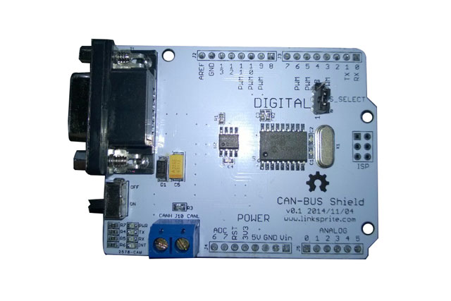
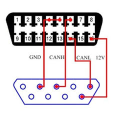
CAN – BUS is a common BUS industry, because of its support for a long distance, medium speed and high reliability of communication. It is often found in modern machine tools and Automotive diagnostic bus.The CAN – BUS expansion board adopt the CAN BUS controller of MCP2515, SPI interface and MCP2551 CAN transceiver, communicate with your Arduino. With OBD II conversion line and the improvement of the OBD II – library, you can create an on-board diagnosis device or data recorder.
- The CAN transfer rate is as high as 1 Mb/s
- SPI interface transmission rate is as high as 10 MHz
- Standard (11bite) and (29 bite) data transmission
- The two have the priority to accept the cache information
- 9-pin industry standard sub – D interface
- Two LED indicators
Specification
Working Voltage: 4.8~5.2V
Size: 68 x 53mm
Schematics
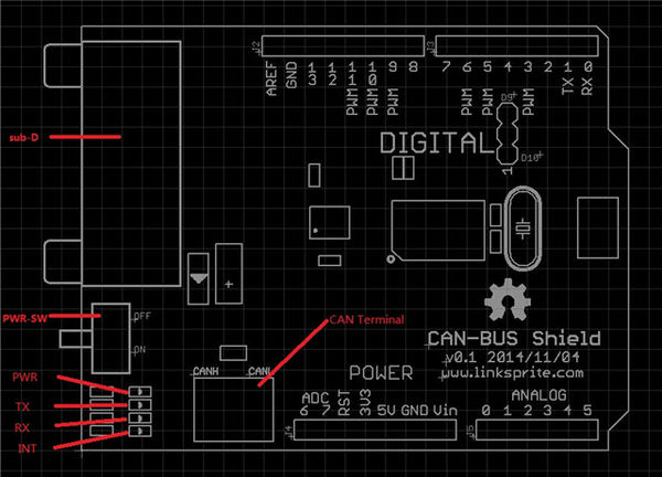
Interface
Usage
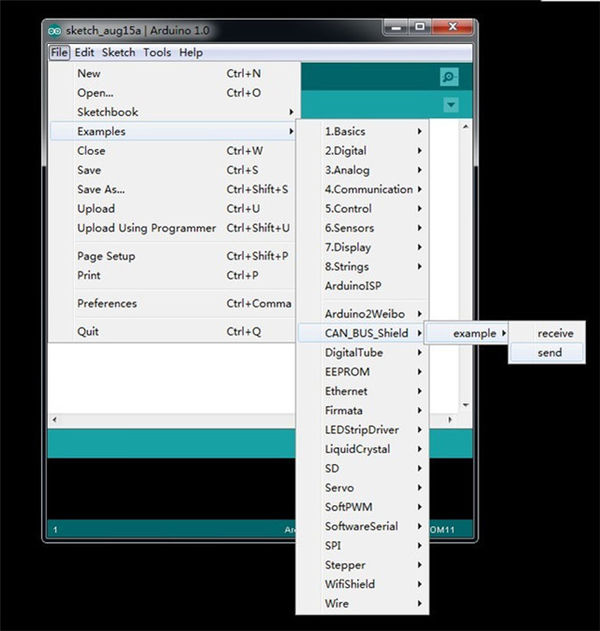
1. Download the CAN_BUS_Shield library, upzip it to this path:..\arduino-1.0\libraries.
2. Open the ”receive” and “send” code,you need two Arduino IDE to open them.
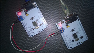
3. Respectively download to two Arduino, record which shield is the "send" and which is "receive" shield.
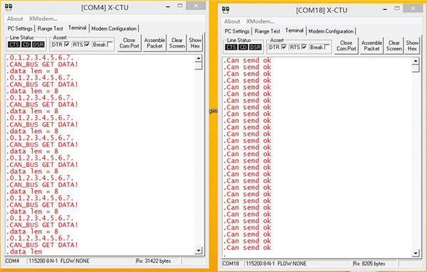
4. Open the serial software tool and set the baud rate to 115200, you can see the result as the following picture( respectively are the output information of receive port (left) and send port (right)).
