Ultrasonic MEMS Sensor SPM0404UD5
Contents
Introduction
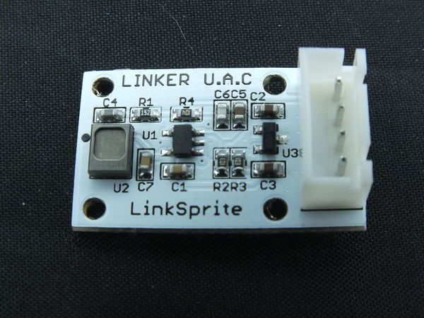
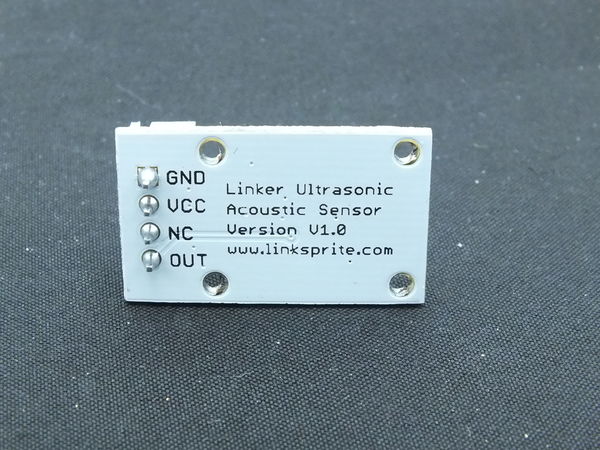
Ultrasonic MEMS Sensor is Knowles Acoustics’ SPM0404UD5 : Mini SiSonic Ultrasonic Acoustic Sensor. This sensor was chosen for its wide and relatively flat pass band response over 10 kHz to 65 kHz.
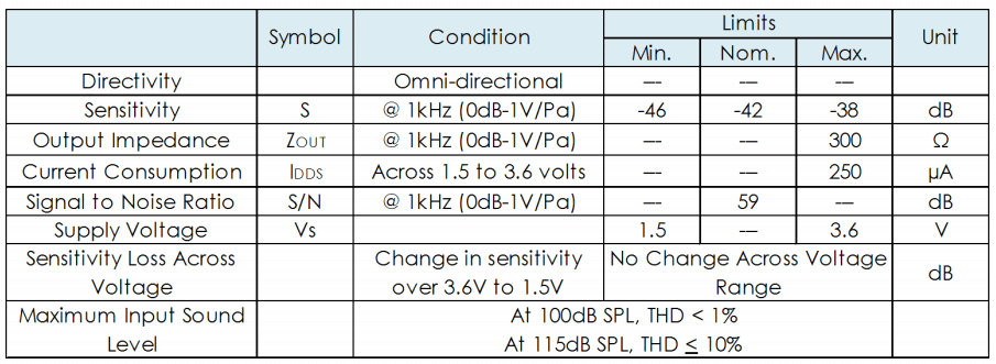
ACOUSTIC & ELECTRICAL SPECIFICATIONS TEST CONDITIONS: +20 C, 60-70% R.H.
Ultrasound is defined as cyclic sound pressure above the frequency limit of human hearing, approximately 20 kHz. This is the most obvious trait of ultrasound, but not necessarily the most important. Depending on application requirements, the user may also be concerned with: Diffraction and packaging effects For many audio devices, the size and shape of the device makes little difference for audio performance. Diffraction starts to become important when a physical object is about 1/4 wavelength in size or larger. At 20 kHz, 1/4 wavelength is about 4 mm; at 100 kHz, 1/4 wavelength is less than 1 mm. For this reason, an ultrasonic microphone is directional, though it has only one acoustic port. The directional pattern depends on how the microphone is packaged and measured. A polar response measurement is required to determine the exact directional pattern at a specific frequency. Propagation loss and absorption Sound intensity decreases by 6 dB with each doubling of distance from a point source. Ultrasound also loses energy quickly due to absorption effects, with absorption increasing along with frequency and humidity. For higher humidity, losses can reach over 3 dB/m at frequencies of 80 kHz.
Measurement and calibration
When performing measurements, the following guidelines should be considered:
Ultrasonic sound source The acoustic bandwidth requirement determines what type of speaker may be used. An ordinary tweeter component may be adequate for measurements up to 50 kHz. Check the component specification. For measurements up to 100 kHz, a specialized speaker is required. One example is the Murata ES-105A (discontinued). Ultrasonic reference microphone For measurements up to 50 kHz, a 1/4 inch reference microphone is recommended. Check with Bruel and Kjaer or GRAS for available types and required equipment. For measurements up to 100 kHz, a 1/8 inch reference microphone is recommended. Check with Bruel and Kjaer or GRAS for available types and required equipment. Calibration measurement Place the test microphone and reference microphone with the sound ports at 90 degree incidence to the speaker at a distance of 1 m. Microphone ports should be placed as close as possible without touching. Sweep the sound source through the frequency range of interest, and compare the reference microphone output to test the microphone output. Calculate the response of the test microphone for the given sound pressure. An audio analyzer may be used to facilitate the measurement.
Use and recording
The use of ultrasonic sensors in listening and recording applications requires consideration of the following:
Equipment used for ultrasonic recording must have adequate frequency bandwidth to avoid filtering out frequencies of interest. Microphone level signals require pre-amplification, so check the specifications for any pre-amplifier used for listening or recording. If using a PC to record ultrasonic signals, verify that the sound card supports sampling rates of at least twice the maximum frequency of interest. Set an adequate sampling rate in the record settings of the recorder program used (such as Adobe Audition or similar).
Typical sensor performance
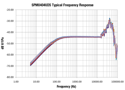
The frequency response for the SPM0404UD5 covers a wide frequency band — from subsonic to ultrasonic (see Figure 2). Specialized equipment is required for measurements at both extremes of the frequency range. The SPM0404UD5 may be used as a sensor, a conventional microphone, or both.
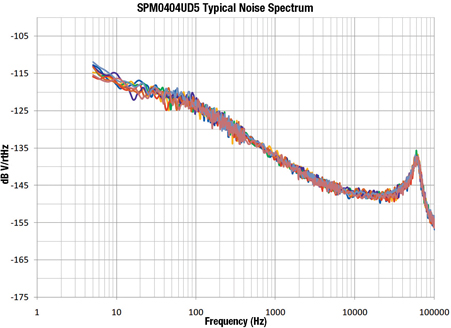
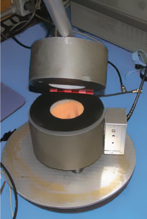
Spectral noise for the SPM0404UD5 is shown in Figure 3. Noise is measured in a sealed heavy steel enclosure that rests on a cushion to limit vibration transmission (see Figure 4).
Low-frequency relative phase
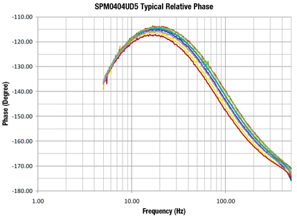
If using the SPM0404UD5 for low frequencies in addition to high frequencies, uniform phase performance may be important for array performance or consistency in feed-forward systems. The measurement in Figure 5 compares the SPM0404UD5 phase noise with the phase noise of a laboratory reference microphone in a sealed cavity.
Typical ultrasonic sensor applications
Typical applications where ultrasonic sensors are used include:
Compare normal versus abnormal acoustic signatures in the frequency domain: Condition monitoring: ultrasonic acoustic sensing may be an attractive option for condition monitoring of objects such as bearings, valves, motors, gears, and pumps for a prediction of failure or need for replacement. Acoustic sensors do not need to be in contact with the equipment. There is typically little, if any, competing signal in the ultrasonic range. Leak detection: an ultrasonic sensor may listen for leak detection in pressure and vacuum systems such as boilers, heat exchangers, condensers, chillers, tanks, pipes, hatches, and hydraulic systems. Electrical detection: arc and corona of electrical apparatus are identified. Time-of-arrival: an array of two or more SPM0404UD5 ultrasonic MEMS sensors may be used to determine the direction/location of an acoustic source/transmitter in near proximity. Event detection: one or more SPM0404UD5 ultrasonic MEMS sensors may be used to detect an event that creates ultrasonic energy, such as an impulse or acoustic shock wave.
