Difference between revisions of "McLaren V1.0"
Katherine.d (talk | contribs) (→Specification) |
Katherine.d (talk | contribs) (→Specification) |
||
| (10 intermediate revisions by the same user not shown) | |||
| Line 48: | Line 48: | ||
== Specification == | == Specification == | ||
| + | === Production Specification === | ||
{| class="wikitable" border="1" | {| class="wikitable" border="1" | ||
|- | |- | ||
| − | | align=" | + | | align="left" style="width:300px"| Product Name |
| − | | align=" | + | | align="left" style="width:400px"| McLaren (Homgplug serial adapter) |
|- | |- | ||
| − | | align=" | + | | align="left" rowspan=6| Interface |
| − | | align=" | + | | align="left"| 3.3V TTL UART; Optional interface cards: |
|- | |- | ||
| − | | align=" | + | | align="left"| RS232 (model/ordering no: UART-RS232) |
|- | |- | ||
| − | | align=" | + | | align="left"| RS485 (model/ordering no: UART-RS485) |
|- | |- | ||
| − | | align=" | + | | align="left"| USB (model/ordering no: UART-USB) |
|- | |- | ||
| − | | align=" | + | | align="left"| Ethernet (model/ordering no: UART-Ethernet) |
|- | |- | ||
| − | | align=" | + | | align="left"| Zigbee (model/ordering no: Xbee) |
|- | |- | ||
| − | | align=" | + | | align="left" rowspan=3| Communication Line Voltage |
| − | | align=" | + | | align="left"| 230VAC/50Hz |
|- | |- | ||
| − | | align=" | + | | align="left"| 110VAC/60Hz |
|- | |- | ||
| − | | align=" | + | | align="left"| 0-400V DC |
|- | |- | ||
| − | | align=" | + | | align="left"| Supply Voltage |
| − | | align=" | + | | align="left"| 5V-12V DC,3A |
|- | |- | ||
| − | | align=" | + | | align="left"| Modulation |
| − | | align=" | + | | align="left"| OFDM (Homeplug 1.0 Compatible) |
|- | |- | ||
| − | | align=" | + | | align="left"| Error Correction |
| − | | align=" | + | | align="left"| FEC(Forward Error Correction) |
|- | |- | ||
| − | | align=" | + | | align="left"| Data rate on Powerline |
| − | | align=" | + | | align="left"| 5Mbps (throughput) |
|- | |- | ||
| − | | align=" | + | | align="left"| Maximum packet data length |
| − | | align=" | + | | align="left"| 300 bytes |
|- | |- | ||
| − | | align=" | + | | align="left"| Transmission distance |
| − | | align=" | + | | align="left"| 300 feets(no repeater) |
|- | |- | ||
| − | | align=" | + | | align="left"| Support nodes number |
| − | | align=" | + | | align="left"| 65535 |
|- | |- | ||
| − | | align=" | + | | align="left" rowspan=3| LED |
| − | | align=" | + | | align="left"| Power Line Activity LED |
|- | |- | ||
| − | | align=" | + | | align="left"| System LED |
|- | |- | ||
| − | | align=" | + | | align="left"| Serial Port LED |
|} | |} | ||
| − | |||
| + | === Command Mode === | ||
| + | |||
| + | *'''Enter Command''' | ||
| + | |||
| + | The module can be put into command mode by sending '''+++''' through serial port. The module will respond with an '''ok'''. In order to prevent the situation where the user data '''+++''' mistakenly triggers the command mode, there must be no serial port data input one second before and after the receiving of '''+++'''. At the same time, the gap between the three '''+''' should not be more than one second, otherwise, it will be considered as a data rather than a command. | ||
| + | |||
| + | *'''Exit command mode''' | ||
| + | |||
| + | There are two approaches to exit command mode. One way is to input command '''ATEX'''. The other is to timeout and automatically exit. In either case, the modules will response '''exited'''. The timeout value can be set by command '''ATTO''' | ||
| + | |||
| + | *'''Arguments and Responses''' | ||
| + | |||
| + | For all the commands with arguments: if the parameters are correct, the module will respond with an '''ok'''. Otherwise, the modules will response with an '''invalid para'''. If there are no arguments associated with the commands, it will be treated as polling modem and the module will respond with the existing arguments residing in the module. | ||
| + | |||
| + | *''' Commands without Arguments''' | ||
| + | |||
| + | There are four commands without arguments: | ||
| + | |||
| + | :*+ + +: enter command mode; will directly return '''ok'''. | ||
| + | :*ATEX: exit the command mode, return '''exited'''. | ||
| + | :*ATRS: software reset, will reset the module immediately, no return. | ||
| + | *'''Modified arguments''' | ||
| + | Except for serial arguments, the modified arguments will be immediately saved into eeprom and take effect. The serial arguments won’t take effect immediately after being modified to avoid user from modifying PC serial arguments before inputting command. Serial arguments will take effect through automatically resetting module when exiting the command mode. | ||
| + | == Pin definition and Rating == | ||
| + | {|class="wikitable" border="1" | ||
| + | |- | ||
| + | ! style="width:100px" |PIN# | ||
| + | ! style="width:100px" |Name | ||
| + | ! style="width:300px" |Direction | ||
| + | ! style="width:600px" |Description | ||
| + | |- | ||
| + | | 1 | ||
| + | | VCC | ||
| + | | - | ||
| + | | 3.3V power supply | ||
| + | |- | ||
| + | | 2 | ||
| + | | DOUT | ||
| + | | Output | ||
| + | | UART Data Out | ||
| + | |- | ||
| + | | 3 | ||
| + | | DIN | ||
| + | | Input | ||
| + | | UART Data In | ||
| + | |- | ||
| + | | 4 | ||
| + | | EX4 | ||
| + | | Depending on model of daughter card | ||
| + | | Route daughtercard final interface signal back to mother board, and to the DIP pins to user’s board | ||
| + | |- | ||
| + | | 5 | ||
| + | | RESET | ||
| + | | Input | ||
| + | | Module Reset | ||
| + | |- | ||
| + | | 6 | ||
| + | | EX3 | ||
| + | | Depending on model of daughter card | ||
| + | | Route daughtercard final interface signal back to mother board, and to the DIP pins to user’s board | ||
| + | |- | ||
| + | | 7 | ||
| + | | EX2 | ||
| + | | Depending on model of daughter card | ||
| + | | Route daughtercard final interface signal back to mother board, and to the DIP pins to user’s board | ||
| + | |- | ||
| + | | 8 | ||
| + | | EX1 | ||
| + | | Depending on model of daughter card | ||
| + | | Route daughtercard final interface signal back to mother board, and to the DIP pins to user’s board | ||
| + | |- | ||
| + | | 9 | ||
| + | | SLEEP | ||
| + | | Input | ||
| + | | Pin Sleep Control Line | ||
| + | |- | ||
| + | | 10 | ||
| + | | GND | ||
| + | | - | ||
| + | | Ground | ||
| + | |- | ||
| + | | 11 | ||
| + | | Unused | ||
| + | | - | ||
| + | | - | ||
| + | |- | ||
| + | | 12 | ||
| + | | Unused | ||
| + | | - | ||
| + | | - | ||
| + | |- | ||
| + | | 13 | ||
| + | | Unused | ||
| + | | - | ||
| + | | - | ||
| + | |- | ||
| + | | 14 | ||
| + | | Unused | ||
| + | | - | ||
| + | | - | ||
| + | |- | ||
| + | | 15 | ||
| + | | Associate | ||
| + | | Output | ||
| + | | Associate Indicator | ||
| + | |- | ||
| + | | 16 | ||
| + | | Unused | ||
| + | | - | ||
| + | | - | ||
| + | |- | ||
| + | | 17 | ||
| + | | Unused | ||
| + | | - | ||
| + | | - | ||
| + | |- | ||
| + | | 18 | ||
| + | | Unused | ||
| + | | - | ||
| + | | - | ||
| + | |- | ||
| + | | 19 | ||
| + | | Unused | ||
| + | | - | ||
| + | | - | ||
| + | |- | ||
| + | | 20 | ||
| + | | Unused | ||
| + | | - | ||
| + | | - | ||
| + | |} | ||
== Mechanic Dimensions == | == Mechanic Dimensions == | ||
| Line 122: | Line 253: | ||
=== Hardware Installation === | === Hardware Installation === | ||
| + | You need to have a pair of the items shown above: | ||
| + | :*McLaren | ||
| + | :*RS232 card or USB card | ||
| + | :*Power line cable used to couple power communication signal to power line, the power line can be 110V/220V 50/60Hz, DC, or unpowered. | ||
| + | :*5V/2A DC | ||
| + | |||
| + | [[File:mclarenv1.1.jpg | 400px]] | ||
| + | |||
| + | === Programming === | ||
| + | |||
| + | You need to install LinkSprite-NEC serial port terminal software that is included in the CD that accompanies the McLaren by clicking '''setup.exe''' | ||
| + | |||
| + | If you are using a USB to RS232 converter, you can use Device Manager tab to find out the COM port. | ||
| + | [[File:mclarenv1.2.jpg | 400px]] | ||
| + | Open LinkSprite-NEC serial port terminal by click program and follow the following: | ||
| + | [[File:mclarenv1.3.jpg | 400px]] | ||
| − | + | LinkSprite-NEC serial port terminal will show up as: | |
| + | |||
| + | [[File:mclarenv1.4.jpg | 400px]] | ||
| + | |||
| + | Click the '''Port Settings''' button to configure the serial port: | ||
| + | |||
| + | [[File:mclarenv1.5.jpg | 400ox]] | ||
| + | From device manager, we know that the COM port we are using is COM17. The default baud rate for McLaren is 9600. Click '''OK''', and Click '''Open COM Port''' to open the COM port. | ||
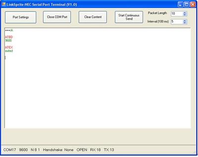
| + | As shown in the following screen, by typing three '''+''' fast, we can enter into AT command mode to configure the module. | ||
| + | [[File:mclarenv1.6.jpg | 400px]] | ||
| + | Next we can click '''Start Continuous Send''' to toggle continuous send and receive. | ||
== FAQ == | == FAQ == | ||
Latest revision as of 09:41, 11 December 2012
Contents
Introduction
LinkSprite’s broadband powerline communication module McLaren are consisted of a McLaren motherboard, UART-RS232 daughter board, UART-RS485 daughter board, UART-USB daughter board, UART-Zigbee daughter board and UART-Ethernet daughter board.
On the McLaren motherboard, there is a 20-pin 2mm spacing receptacle, users can choose different daughter boards based on the interface needs.
The McLaren motherboard also support DIP by optional pins that can be used to directly plug to user’s board without doing screwing. The interface board signals such as RS232/RS485/USB signals are also routed back to motherboard through the 20-pin receptacle, and again to users’ board through these DIP pins.
McLaren are transceiver modules designed to send / receiver serial data over the powerline network. McLaren is designed to transparently move serial data over the powerline network, and achieves the target of replacing cables by the ubiquitous powerline network.
Features
- AC and DC powerline Communications
- Fully transparent mode, plug and play coming out of the box without the need to do any programming.
- HomePlug1.0
- 5Mbps throughput on the power line
- Built-in error correction codes.
- Built-in repeater function to extend the coverage.
- Physical and logic address
- AT commands used for advanced configuration.
- 3.3V TTL UART, Optional RS232, RS485. USB, Ethernet, Zigbee interfaces
- Low power
- RoHS
Application Ideas
- AMR
- Industry manufacture and control
- Safeguard, fire alarm, smoke alarm
- Collect and transmit instrument data
- Safeguard and monitor
- Home automation
- Solar/Wind electricity generation system
- Low latency servo control
Cautions
Schematic
Specification
Production Specification
| Product Name | McLaren (Homgplug serial adapter) |
| Interface | 3.3V TTL UART; Optional interface cards: |
| RS232 (model/ordering no: UART-RS232) | |
| RS485 (model/ordering no: UART-RS485) | |
| USB (model/ordering no: UART-USB) | |
| Ethernet (model/ordering no: UART-Ethernet) | |
| Zigbee (model/ordering no: Xbee) | |
| Communication Line Voltage | 230VAC/50Hz |
| 110VAC/60Hz | |
| 0-400V DC | |
| Supply Voltage | 5V-12V DC,3A |
| Modulation | OFDM (Homeplug 1.0 Compatible) |
| Error Correction | FEC(Forward Error Correction) |
| Data rate on Powerline | 5Mbps (throughput) |
| Maximum packet data length | 300 bytes |
| Transmission distance | 300 feets(no repeater) |
| Support nodes number | 65535 |
| LED | Power Line Activity LED |
| System LED | |
| Serial Port LED |
Command Mode
- Enter Command
The module can be put into command mode by sending +++ through serial port. The module will respond with an ok. In order to prevent the situation where the user data +++ mistakenly triggers the command mode, there must be no serial port data input one second before and after the receiving of +++. At the same time, the gap between the three + should not be more than one second, otherwise, it will be considered as a data rather than a command.
- Exit command mode
There are two approaches to exit command mode. One way is to input command ATEX. The other is to timeout and automatically exit. In either case, the modules will response exited. The timeout value can be set by command ATTO
- Arguments and Responses
For all the commands with arguments: if the parameters are correct, the module will respond with an ok. Otherwise, the modules will response with an invalid para. If there are no arguments associated with the commands, it will be treated as polling modem and the module will respond with the existing arguments residing in the module.
- Commands without Arguments
There are four commands without arguments:
- + + +: enter command mode; will directly return ok.
- ATEX: exit the command mode, return exited.
- ATRS: software reset, will reset the module immediately, no return.
- Modified arguments
Except for serial arguments, the modified arguments will be immediately saved into eeprom and take effect. The serial arguments won’t take effect immediately after being modified to avoid user from modifying PC serial arguments before inputting command. Serial arguments will take effect through automatically resetting module when exiting the command mode.
Pin definition and Rating
| PIN# | Name | Direction | Description |
|---|---|---|---|
| 1 | VCC | - | 3.3V power supply |
| 2 | DOUT | Output | UART Data Out |
| 3 | DIN | Input | UART Data In |
| 4 | EX4 | Depending on model of daughter card | Route daughtercard final interface signal back to mother board, and to the DIP pins to user’s board |
| 5 | RESET | Input | Module Reset |
| 6 | EX3 | Depending on model of daughter card | Route daughtercard final interface signal back to mother board, and to the DIP pins to user’s board |
| 7 | EX2 | Depending on model of daughter card | Route daughtercard final interface signal back to mother board, and to the DIP pins to user’s board |
| 8 | EX1 | Depending on model of daughter card | Route daughtercard final interface signal back to mother board, and to the DIP pins to user’s board |
| 9 | SLEEP | Input | Pin Sleep Control Line |
| 10 | GND | - | Ground |
| 11 | Unused | - | - |
| 12 | Unused | - | - |
| 13 | Unused | - | - |
| 14 | Unused | - | - |
| 15 | Associate | Output | Associate Indicator |
| 16 | Unused | - | - |
| 17 | Unused | - | - |
| 18 | Unused | - | - |
| 19 | Unused | - | - |
| 20 | Unused | - | - |
Mechanic Dimensions
Usage
Hardware Installation
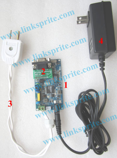
You need to have a pair of the items shown above:
- McLaren
- RS232 card or USB card
- Power line cable used to couple power communication signal to power line, the power line can be 110V/220V 50/60Hz, DC, or unpowered.
- 5V/2A DC
Programming
You need to install LinkSprite-NEC serial port terminal software that is included in the CD that accompanies the McLaren by clicking setup.exe
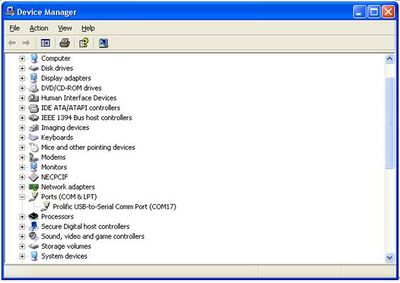
If you are using a USB to RS232 converter, you can use Device Manager tab to find out the COM port.
Open LinkSprite-NEC serial port terminal by click program and follow the following:
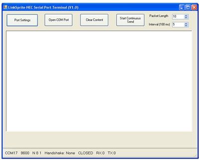
LinkSprite-NEC serial port terminal will show up as:
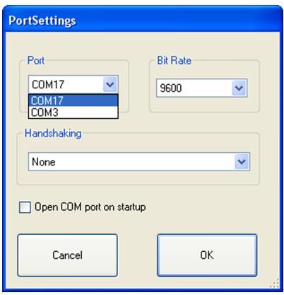
Click the Port Settings button to configure the serial port:
From device manager, we know that the COM port we are using is COM17. The default baud rate for McLaren is 9600. Click OK, and Click Open COM Port to open the COM port.
As shown in the following screen, by typing three + fast, we can enter into AT command mode to configure the module.
Next we can click Start Continuous Send to toggle continuous send and receive.
FAQ
Please list your question here:
Support
If you have questions or other better design ideas, you can go to our forum to discuss or creat a ticket for your issue at linksprite support.
Resources
How to buy
See Also
Other related products and resources.
Licensing
This documentation is licensed under the Creative Commons Attribution-ShareAlike License 3.0 Source code and libraries are licensed under GPL/LGPL, see source code files for details.
