Difference between revisions of "LinkerBot Platform"
Katherine.d (talk | contribs) (→Step 4) |
Katherine.d (talk | contribs) (→Step 2) |
||
| (One intermediate revision by the same user not shown) | |||
| Line 80: | Line 80: | ||
===Step 2=== | ===Step 2=== | ||
[[File:Step2.jpg | 400px]] | [[File:Step2.jpg | 400px]] | ||
| − | *Install the speed encoder, and fix | + | *Install the speed encoder, and fix the motor to the plastic sheet |
Attention: The motor lead should be faced to inside, the speed ebcoder side, cannot install reversed | Attention: The motor lead should be faced to inside, the speed ebcoder side, cannot install reversed | ||
| Line 92: | Line 92: | ||
===Step 5=== | ===Step 5=== | ||
| − | [[File:Step5.jpg]] | + | [[File:Step5.jpg | 400px]] |
*Insert the copper cylinder, fix the Omni-directional ball caster metal by 8 screws. Pinch the motor(to protect the fixture), then insert it into wheel. Assemble finish. | *Insert the copper cylinder, fix the Omni-directional ball caster metal by 8 screws. Pinch the motor(to protect the fixture), then insert it into wheel. Assemble finish. | ||
| − | [[File:effect.jpg]] | + | [[File:effect.jpg | 400px]] |
Latest revision as of 06:57, 30 November 2012
The LinkerBot platform is a kit which has the following features:
- Simple mechanical structure, and easy to assemble. The assembling instructions are provided.
- Speed encoders are embedded. They can be used to measure the walking distance, speed feedback, etc.
- Battery holder is provided that can hold 4 AA batteries.
- A switch is provided so that user can easily power on and off.
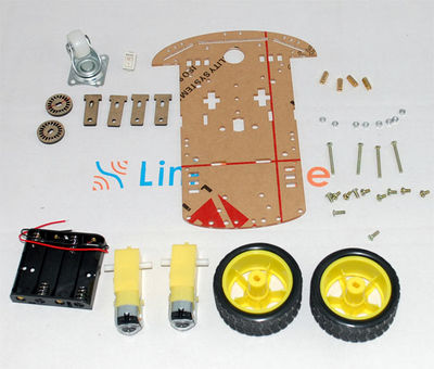
Parts List:
- 1 x Plastic sheet
- 2 x Electric motors
- 2 x Speed encoders
- 4 x Fixtures
- 1 x Omni-directional ball caster metal
- 1 x Battery holder
- 1 x Switch
- Many nuts and bolts
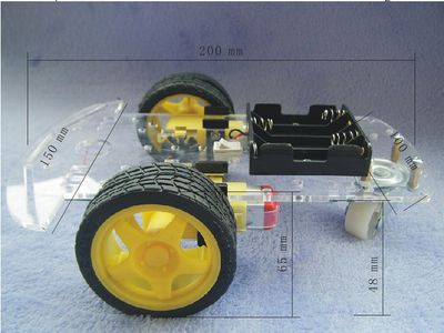
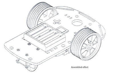
After assembling, it will look as:
The distance between inner rings of tires is 130mm. The distance between outer rings of tires is 150mm.
LinkerBot comes with speed encoder that can be used to measure the speed.
Contents
Specification of Motor
| Working Voltage | DC 3V | DC 5V | DC 6V |
|---|---|---|---|
| Working Current | 100mA | 100mA | 120mA |
| Gear Ratio | 48:1 | ||
| Idle Speed (loaded with tire) | 100 rpm | 190 rpm | 240 rpm |
| Diameter of Tire | 6.6cm | ||
| Idle Linear Speed | 20 meters/minute | 39 meters/minute | 48 meters/minute |
| Weight | 50g | ||
| Size | 70mm X 22mm X 18mm | ||
| Noise | < 65dB | ||
Assembly Instruction
Step 1
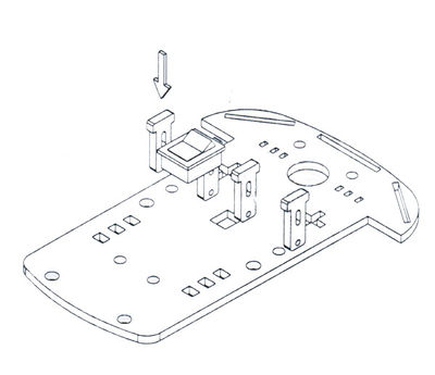
- Remove the protection paper of plastic sheet, fixture, and speed encoder.
- Insert fixture into the plastic sheet
Step 2
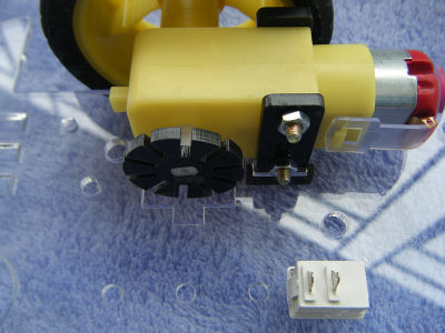
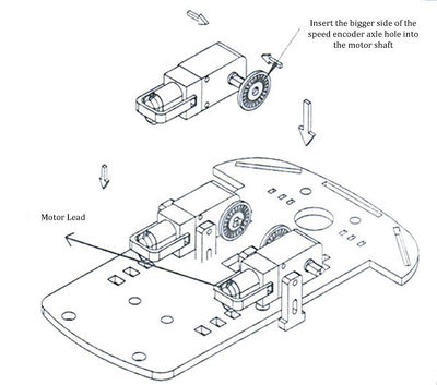
- Install the speed encoder, and fix the motor to the plastic sheet
Attention: The motor lead should be faced to inside, the speed ebcoder side, cannot install reversed
Step 3
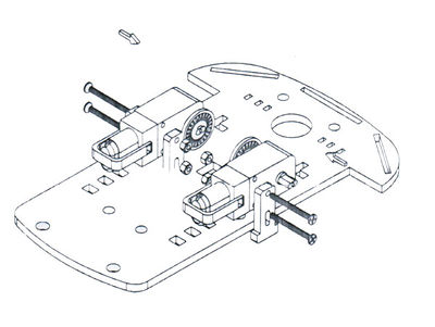
- Fix the motor to the plastic sheet, insert the screws then tight up the nults
Step 4
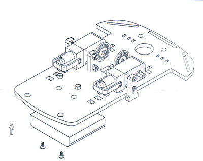
- Insert the screws, and fasten the battery holder
Step 5
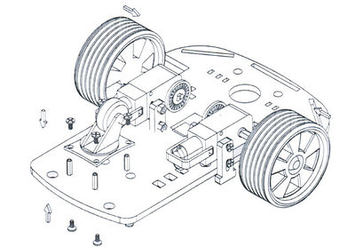
- Insert the copper cylinder, fix the Omni-directional ball caster metal by 8 screws. Pinch the motor(to protect the fixture), then insert it into wheel. Assemble finish.
