Difference between revisions of "PcDuino4 Nano"
(→Introduction) |
(→Resouces) |
||
| Line 25: | Line 25: | ||
*Dimensions – 64 x 50mm (Orange Pi One dimensions: 69mm × 48mm) | *Dimensions – 64 x 50mm (Orange Pi One dimensions: 69mm × 48mm) | ||
| − | == | + | == Features == |
| + | |||
| + | *CPU: Allwinner H3, Quad-core Cortex-A7@1.2GHz | ||
| + | |||
| + | *GPU: Mali400MP2@600MHz,Supports OpenGL ES2.0 | ||
| + | |||
| + | *DDR3 RAM: 1GB | ||
| + | |||
| + | *Connectivity: 10\/100M Ethernet | ||
| + | |||
| + | *Audio: 3.5mm audio jack\/Via HDMI | ||
| + | |||
| + | *Microphone: Onboard microphone | ||
| + | |||
| + | *IR Receiver: Onboard IR receiver | ||
| + | |||
| + | *USB Host:Type A, USB 2.0 x 3 | ||
| + | |||
| + | *MicroSD Slot x 1 | ||
| + | |||
| + | *MicroUSB: for data transmission and power input, OTG | ||
| + | |||
| + | *Video Output: HDMI 1.4 1080P, CVBS | ||
| + | |||
| + | *DVP Camera Interface: 24pin, 0.5mm pitch FPC seat | ||
| + | |||
| + | *Debug Serial Port: 4Pin, 2.54mm pitch pin header | ||
| + | |||
| + | *GPIO: 2.54mm spacing 40pin, compatible with Raspberry Pi's GPIO. It includes UART, SPI, I2C, IO etc | ||
| + | |||
| + | *User Key: Power LED x 1, Reset x 1 | ||
| + | |||
| + | *PC Size: 64 x 50mm | ||
| + | |||
| + | *Power Supply: DC 5V\/2A | ||
| + | |||
| + | *OS\/Software: u-boot,Ubuntu MATE,Debian | ||
| + | |||
| + | == GPIOs Sepc == | ||
| + | |||
| + | === GPIO40 === | ||
| + | |||
| + | [[File:pc4 nona GPIO40.jpg|640px]] | ||
| + | |||
| + | === Debug port === | ||
| + | |||
| + | [[File:pc4 nano Debug port.jpg|640px]] | ||
| + | |||
| + | === DVP Camera IF Pin Spec === | ||
| + | |||
| + | [[File:pc4 nano DVP.jpg|640px]] | ||
| + | |||
| + | '''Note:''' | ||
| + | |||
| + | *SYS_3.3V: 3.3V power output | ||
| + | |||
| + | *VDD_5V: 5V power input\/output. When the external device’s power is greater than the MicroUSB’s the external device is charging the board otherwise the board | ||
| + | powers the external device. The input range is 4.7V ~ 5.6V | ||
| + | |||
| + | *All pins are 3.3V and output current is 5mA. It can drive small loads. No IO pins can drive a load. | ||
| + | |||
| + | == Get Started == | ||
| + | |||
| + | 1.8G (or bigger) TF card( Speed class is recommended for Class 6 or higher) | ||
| + | |||
| + | 2.TF card reader | ||
| + | |||
| + | 3.[https://s3.amazonaws.com/linksprite/pcduino/pcduino4-nano-debian-20160903.img.7z Debian for pcDuino4 nano] | ||
| + | |||
| + | 4.Windows tool: [https://s3.amazonaws.com/pcduino/Tools/win32diskimager-v0.7-binary.zip Win32DiskImager] | ||
| + | |||
| + | [[File:win32disk.png|540px]] | ||
| + | |||
| + | === 1. Make a Bootable SD Card === | ||
| + | |||
| + | *Plug TF Card Reader into Windows PC and open Win32DiskImager as administrator. | ||
| + | |||
| + | *Select the Image File that you unzip from the downloaded File | ||
| + | |||
| + | *Select the Device that the PC recognized | ||
| + | |||
| + | *Click the write button. | ||
| + | |||
| + | *It will say Write Successful at the end. | ||
| + | |||
| + | '''Tips:''' If you only have Linux or Mac OS, how to create a bootable SD card? Only dd command is needed. | ||
| + | sudo dd if=<image-file>.img of=/dev/<your SD card disk> bs=1M | ||
| + | |||
| + | *if=should be your downloaded system img file | ||
| + | |||
| + | *of=should be your micro-SD card. | ||
| + | |||
| + | === 2. Boot your system === | ||
| + | |||
| + | *Insert this card into your pcDuino4 nano's BOOT slot | ||
| + | |||
| + | *Power on (with a 5V\/2A power source). | ||
| + | |||
| + | *If the green LED is on and the blue LED is blinking this indicates your pcDuino4 nano has successfully booted. | ||
| + | |||
| + | '''Note''': | ||
| + | |||
| + | The default of username and password are all: '''ls''' | ||
| + | |||
| + | === 3. Remove Desktop Access via VNC === | ||
| + | |||
| + | *If you want to access the Debian system using VNC, please take the following information: | ||
| + | |||
| + | **Default Port : '''5901''' | ||
| + | |||
| + | **Password: '''ls123456''' | ||
| + | |||
| + | [[File:vnc.png|540px]] | ||
| + | |||
| + | [[File:screen.png|540px]] | ||
| + | |||
| + | === Tips === | ||
| + | |||
| + | ==== 1. Extend TF Card's rootfs Section ==== | ||
| + | |||
| + | Resize the rootfs section of the TF card run the following commands on the pcDuino4 Nano's Debian terminal: | ||
| + | |||
| + | sudo fs_resize | ||
| + | |||
| + | Following the prompt type in "y" to start re-sizing the file system and a second "y" to reboot the pcDuino4 Nano. | ||
| + | |||
| + | ==== 2. Ethernet Connection ==== | ||
| + | |||
| + | If the pcDuino4 Nano is connected to a network via Ethernet before it is powered on it will automatically obtain an IP after it is powered up. If it is not connected via Ethernet or its DHCP is not activated obtaining an IP will fail and system will hang on for about 15 to 60 seconds | ||
| + | |||
| + | The pcDuino4 Nano by default doesn't have a valid MAC address. If the board connects a network successfully it will automatically generates a random MAC in /etc/network/interfaces.d/eth0 | ||
| + | |||
| + | Users can change it to a self-defined valid one:vi \/etc\/network\/interfaces.d\/eth0 | ||
| + | |||
| + | Here is the content of a sample configuration file: | ||
| + | |||
| + | auto eth0 | ||
| + | allow-hotplug eth0 | ||
| + | iface eth0 inet dhcp | ||
| + | hwaddress 76:92:d4:85:f3:0f | ||
| + | |||
| + | The '''hwaddress''' specifies the MAC address. Here the '''76:92:d4:85:f3:0f''' is a random MAC. We suggest users change it to a valid one. '''Note:''' when you reset the MAC please make sure your MAC meets IEEE's definition otherwise it will cause unexpected issues. After you make your change, save, exit and reboot your board or run the following commands to restart the network: | ||
| + | |||
| + | systemctl restart networking | ||
| + | |||
| + | ==== 3. HDMI resolution ==== | ||
| + | |||
| + | Our Debian system's HDMI resolution is set by a script.bin file in the root directory of the installation TF card's boot section. By default the resolution is '''1080P60'''. There are multiple script.bin files under that directory for different resolutions. For example if you want to modify the resolution to 720P60 you can use the script-720p-60.bin file to replace the existing one by using the following command: | ||
| + | |||
| + | # in TF card boot partition | ||
| + | sudo cp script/script-720p-60.bin ./script.bin | ||
| + | |||
| + | ==== 4. HDMI Audio Output ==== | ||
| + | |||
| + | Our Debian system's default audio output is the 3.5mm audio jack. You can turn on the HDMI audio by editting the \/etc\/asound.conf file: | ||
| + | |||
| + | pcm.!default { | ||
| + | type hw | ||
| + | card 1 | ||
| + | device 0 | ||
| + | } | ||
| + | ctl.!default { | ||
| + | type hw | ||
| + | card 1 | ||
| + | } | ||
| + | |||
| + | card 0 points to the 3.5mm audio jack and card 1 points to the HDMI audio. You need to save your changes and reboot your system to make your changes take effect. | ||
| + | |||
| + | ==== 5. Test GPU ==== | ||
| + | |||
| + | After Debian loads please login from a terminal and run '''glmark2-es2''': | ||
| + | |||
| + | glmark2-e | ||
| + | |||
| + | ==== 6. USB WiFi ==== | ||
| + | |||
| + | Our Debian system has support for popular USB WiFi drivers. Many USB WiFi modules are plug and play with our system. Here is a list of models we tested; | ||
| + | |||
| + | [[File:pc4 nano USB WIFI.jpg|640px]] | ||
| + | |||
| + | If you pcDuino4 Nano is connected to a USB WiFi and is powered up you can log into pcDuino4 Nano and run the following command to check if the USB WiFi is recognized. If "wlan0" is listed it indicates your USB WiFi has been recognized: | ||
| + | |||
| + | ifconfig -a | ||
| + | |||
| + | Open the \/etc\/wpa_supplicant\/wpa_supplicant.conf file and append the following lines: | ||
| + | |||
| + | network={ | ||
| + | ssid="YourWiFiESSID" | ||
| + | psk="YourWiFiPassword" | ||
| + | } | ||
| + | |||
| + | The '''YourWiFiESSID''' and '''YourWiFiPassword''' need to be replaced with your actual SSID and password. | ||
| + | Save, exit and run the following commands to connect to your WiFi router: | ||
| + | |||
| + | ifdown wlan0 | ||
| + | ifup wlan0 | ||
| + | |||
| + | If your WiFi password has special characters or you don't want your password saved as plain text you can use "wpa_passphrase" to generate a psk for your WiFi password. Here is how you can do it: | ||
| + | |||
| + | wpa_passphrase YourWiFiSSID | ||
| + | |||
| + | Following the prompt type in your password and you will get a new password in the \/etc\/wpa_supplicant\/wpa_supplicant.conf file. Now you can replace the existing password in the wlan0 file with the new one. | ||
| + | |||
| + | == Resoures == | ||
| + | |||
| + | [https://s3.amazonaws.com/linksprite/pcduino/pcduino4-nano/pcDuino4-Nano-Schematic.pdf pcDuino4 Nano Schematic] | ||
| + | |||
| + | [https://s3.amazonaws.com/linksprite/pcduino/pcduino4-nano/pcDuino4-Nano-dimensions.dxf pcDuino4 Nano DXF file] | ||
| + | |||
| + | [[File:https://s3.amazonaws.com/linksprite/pcduino/pcduino4-nano/Allwinner_H3_Datasheet_V1.2.pdf Allwinner H3 datasheet]] | ||
| + | |||
| + | [https://s3.amazonaws.com/linksprite/pcduino/pcduino4-nano-debian-20160903.img.7z Debian image file for pcDuino4 Nano] | ||
Revision as of 01:48, 23 September 2016
Introduction
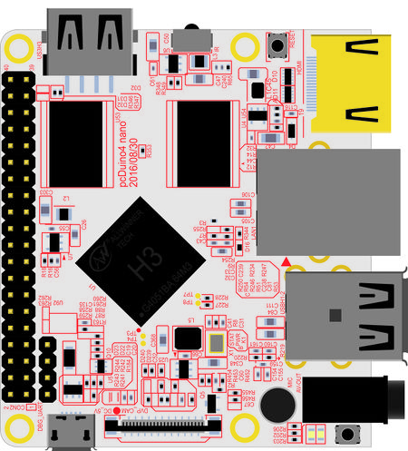
The pcDuino4 Nano is an Allwinner H3 based ARM board designed and released by LinkSprite for hobbyists, makers and electronic fans. It is only two thirds the size of the Raspberry Pi. It is open source. It works with Ubuntu MATE, Debian and etc.
The pcDuino4 Nano uses the Allwinner H3 Soc. It integrates Ethernet, IR receiver, video\/audio output and supports HDMI and AVOUT. It can be powered via the MicroUSB port.
In such a small board it still integrates rich interfaces and ports. Besides the popular HDMI, Ethernet, USB-Host, USB-OTG, DVP camera interface and AVOUT (audio and video) it has an onboard Microphone, IR receiver, a serial debug port and a Raspberry Pi compatible 40 pin GPIO pin header.
Specification
- SoC – Allwinner H3 quad core Cortex A7 @ 1.2 GHz with an ARM Mali-400MP2 GPU up to 600 MHz
- System Memory – 1GB DDR3 SDRAM
- Storage – micro SD card slot
- Video & Audio Output – HDMI and 3.5mm jack for CVBS (composite + stereo audio)
- Connectivity -10/100M Ethernet
- USB – 3x USB 2.0 host ports, 1x micro USB OTG port
- Camera – DVP Interface
- Expansions – 40-pin Raspberry Pi compatible header with UART, SPI, I2C, PWM, GPIOs, etc…
- Debugging – 4-pin header for serial console
- Misc – Power and reset buttons; 2x LEDs; IR receiver; on-board microphone.
- Power Supply – 5V/2A via micro USB port; 4.7V ~ 5.6V via VDD pin on “Raspberry Pi” header.
- Dimensions – 64 x 50mm (Orange Pi One dimensions: 69mm × 48mm)
Features
- CPU: Allwinner H3, Quad-core Cortex-A7@1.2GHz
- GPU: Mali400MP2@600MHz,Supports OpenGL ES2.0
- DDR3 RAM: 1GB
- Connectivity: 10\/100M Ethernet
- Audio: 3.5mm audio jack\/Via HDMI
- Microphone: Onboard microphone
- IR Receiver: Onboard IR receiver
- USB Host:Type A, USB 2.0 x 3
- MicroSD Slot x 1
- MicroUSB: for data transmission and power input, OTG
- Video Output: HDMI 1.4 1080P, CVBS
- DVP Camera Interface: 24pin, 0.5mm pitch FPC seat
- Debug Serial Port: 4Pin, 2.54mm pitch pin header
- GPIO: 2.54mm spacing 40pin, compatible with Raspberry Pi's GPIO. It includes UART, SPI, I2C, IO etc
- User Key: Power LED x 1, Reset x 1
- PC Size: 64 x 50mm
- Power Supply: DC 5V\/2A
- OS\/Software: u-boot,Ubuntu MATE,Debian
GPIOs Sepc
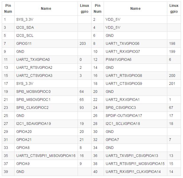
GPIO40
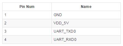
Debug port
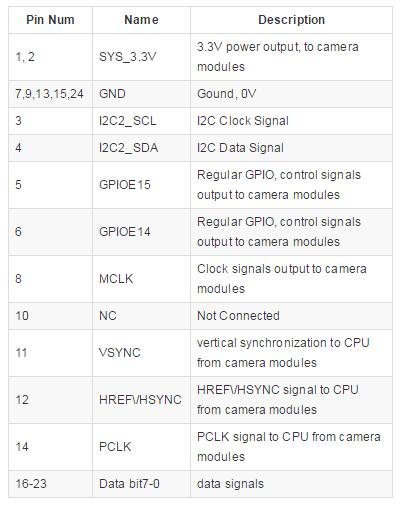
DVP Camera IF Pin Spec
Note:
- SYS_3.3V: 3.3V power output
- VDD_5V: 5V power input\/output. When the external device’s power is greater than the MicroUSB’s the external device is charging the board otherwise the board
powers the external device. The input range is 4.7V ~ 5.6V
- All pins are 3.3V and output current is 5mA. It can drive small loads. No IO pins can drive a load.
Get Started
1.8G (or bigger) TF card( Speed class is recommended for Class 6 or higher)
2.TF card reader
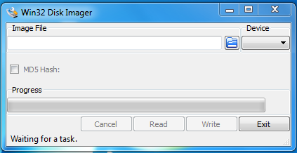
4.Windows tool: Win32DiskImager
1. Make a Bootable SD Card
- Plug TF Card Reader into Windows PC and open Win32DiskImager as administrator.
- Select the Image File that you unzip from the downloaded File
- Select the Device that the PC recognized
- Click the write button.
- It will say Write Successful at the end.
Tips: If you only have Linux or Mac OS, how to create a bootable SD card? Only dd command is needed.
sudo dd if=<image-file>.img of=/dev/<your SD card disk> bs=1M
- if=should be your downloaded system img file
- of=should be your micro-SD card.
2. Boot your system
- Insert this card into your pcDuino4 nano's BOOT slot
- Power on (with a 5V\/2A power source).
- If the green LED is on and the blue LED is blinking this indicates your pcDuino4 nano has successfully booted.
Note:
The default of username and password are all: ls
3. Remove Desktop Access via VNC
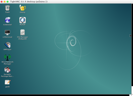
- If you want to access the Debian system using VNC, please take the following information:
- Default Port : 5901
- Password: ls123456
Tips
1. Extend TF Card's rootfs Section
Resize the rootfs section of the TF card run the following commands on the pcDuino4 Nano's Debian terminal:
sudo fs_resize
Following the prompt type in "y" to start re-sizing the file system and a second "y" to reboot the pcDuino4 Nano.
2. Ethernet Connection
If the pcDuino4 Nano is connected to a network via Ethernet before it is powered on it will automatically obtain an IP after it is powered up. If it is not connected via Ethernet or its DHCP is not activated obtaining an IP will fail and system will hang on for about 15 to 60 seconds
The pcDuino4 Nano by default doesn't have a valid MAC address. If the board connects a network successfully it will automatically generates a random MAC in /etc/network/interfaces.d/eth0
Users can change it to a self-defined valid one:vi \/etc\/network\/interfaces.d\/eth0
Here is the content of a sample configuration file:
auto eth0
allow-hotplug eth0
iface eth0 inet dhcp
hwaddress 76:92:d4:85:f3:0f
The hwaddress specifies the MAC address. Here the 76:92:d4:85:f3:0f is a random MAC. We suggest users change it to a valid one. Note: when you reset the MAC please make sure your MAC meets IEEE's definition otherwise it will cause unexpected issues. After you make your change, save, exit and reboot your board or run the following commands to restart the network:
systemctl restart networking
3. HDMI resolution
Our Debian system's HDMI resolution is set by a script.bin file in the root directory of the installation TF card's boot section. By default the resolution is 1080P60. There are multiple script.bin files under that directory for different resolutions. For example if you want to modify the resolution to 720P60 you can use the script-720p-60.bin file to replace the existing one by using the following command:
# in TF card boot partition
sudo cp script/script-720p-60.bin ./script.bin
4. HDMI Audio Output
Our Debian system's default audio output is the 3.5mm audio jack. You can turn on the HDMI audio by editting the \/etc\/asound.conf file:
pcm.!default {
    type hw
    card 1
    device 0
}
ctl.!default {
    type hw
    card 1
}
card 0 points to the 3.5mm audio jack and card 1 points to the HDMI audio. You need to save your changes and reboot your system to make your changes take effect.
5. Test GPU
After Debian loads please login from a terminal and run glmark2-es2:
glmark2-e
6. USB WiFi
Our Debian system has support for popular USB WiFi drivers. Many USB WiFi modules are plug and play with our system. Here is a list of models we tested;
If you pcDuino4 Nano is connected to a USB WiFi and is powered up you can log into pcDuino4 Nano and run the following command to check if the USB WiFi is recognized. If "wlan0" is listed it indicates your USB WiFi has been recognized:
ifconfig -a
Open the \/etc\/wpa_supplicant\/wpa_supplicant.conf file and append the following lines:
network={
    ssid="YourWiFiESSID"
    psk="YourWiFiPassword"
}
The YourWiFiESSID and YourWiFiPassword need to be replaced with your actual SSID and password. Save, exit and run the following commands to connect to your WiFi router:
ifdown wlan0
ifup wlan0
If your WiFi password has special characters or you don't want your password saved as plain text you can use "wpa_passphrase" to generate a psk for your WiFi password. Here is how you can do it:
wpa_passphrase YourWiFiSSID
Following the prompt type in your password and you will get a new password in the \/etc\/wpa_supplicant\/wpa_supplicant.conf file. Now you can replace the existing password in the wlan0 file with the new one.
